Klystron Power Supply generates Voltage required for driving the reflex Klystron Tube like 2k25 ( a Source of Microwave energy ). It is absolutely stable, regulated and saw tooth generators, for amplitude and frequency modulation.
| Model | TLKPS-204 |
|---|---|
| Beam Supply | |
| Voltage Range | 200 – 450 V Continuously Variable |
| Current | 50mA Max |
| Regulation | Better Than 0.5% for ± 10% variation in mains Supply Voltage |
| Ripple | Less than 5mV rms |
| Repeller Supply | |
| Voltage Range | -10V to -270V DC continuously Variable with respect to Klystron cathode |
| Regulation | 0.25% for ± 10% variation in mains Supply Voltage. |
| Heater Supply | 6.3V DC (regulated) |
| Modulation | |
| Square Wave | Freq.: 500 Hz-2000Hz Max. Amp. + 110 Volt peak to peak Amplitude and frequency continuously variable |
| Sawtooth | Freq.: 50Hz – 150Hz Amplitude – 60 V Max: peak to peak Amplitude and frequency continuously variable |
| Operation Voltage | 230 V ± 10%, 50 Hz. A.C. |
| Voltage Range | 0 to 12 Volts Variable |
| Current | 1 Amp. Max |
| Regulation | 0.2% for ± 10% variation in the Mains Supply Voltage |
| Ripple | 1M V rms |
| Modulation Frequency | 1KHz ± 10% (900-1100Hz) |
| Output Connector | BNC (F) for Gunn Oscillator & TNC (F) for Pin Modulator |
| Sensitivity | 0.2µ V at a 200 Ohms input impedance for full scale deflection. |
| Noise Level | At least 5 dB below full scale at rated sensitivity and maximum band width With input terminated in 100 ohms and 500 ohms for crystal low and high respectively. |
| Calibration | Square law, meter indicates SWR, dB. |
| Range | 70 db, Input attenuator provides 60dB in 10 dB steps, accuracy ± 0.2 dB per 10 dB steps Maximum Cummulative error ± 0.5dB. |
| Scales Selector | “Normal”, “Expand” and -5 dB. |
| Meter Scale | SWR1-4, SWR 3-10, expand SWR 1 1-3, dB 0-10, expand dB 0-2 |
| Gain Control | Adjusts the reference level, variable range 0-10 db approx. |
| Input | “Bolo” bias provided for 4.3 mA low current bolo meters. “Crystal” 200 ohms for low impedance crystal rectifier & 200 K ohms high impedance crystal rectifier as null detector |
| Recorder Output | Socket provided for recording having 1 V for full scale deflection. Internal resistance of 1000 ohms or less |
| A/C Output | BNC Connector for amplified output. |
| Input Connector | BNC (F) |
| Frequency | 1000Hz ± 10% |
| Power | 230 volts A.C. ± 10%, 50 Hz, mains supply. |
| Sensitivity | 0.2µ V for full scale deflection at maximum bandwidth on low impedance crystal input. |
| Noise Level | At least 5 dB below full scale at rated sensitivity and maximum band width With input terminated in 100 ohms or 500 ohms for crystal low and high respectively. |
| Range | 70 db, in 10 dB and 2 dB steps. |
| Range Accuracy | 0.1 dB per 10dB steps |
| Input | Unbiased low and high impedance crystal, biased crystal (200Ω 200K) Low and high current bolometers (4.5 & 8.7 mA) (200 ohm) |
| Input Frequency | 1 KHz adjustable ± 10% by front panel control. |
| Band Width | Variable 25 Hz to 110 Hz. |
| Meter Scale | SWR1-4, SWR 3-10, expand SWR 1 1-3, dB 0-10, expand dB 0-2 |
| Gain Control | Adjusts the reference level, variable range 0-10 db approx. |
| Recorder Output | 0-1V DC, output connector, Banana Socket. |
| Amplifier output | 0-0.3 Vrms into atleast 10K ohms, output connector BNC (F) |
| Input Connector | BNC (F) |
| Power | 230 volts A.C. ± 10%, 50 Hz, mains supply. |
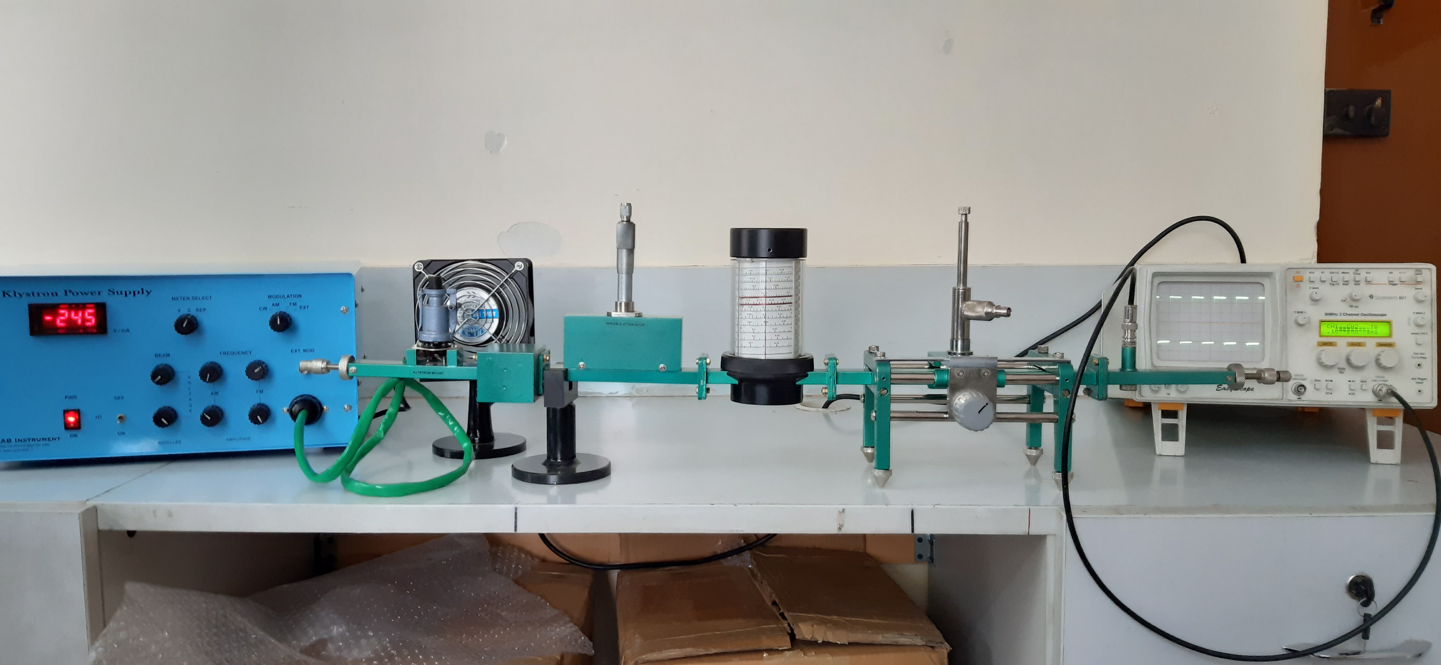
| Sl.No | KLYSTRON BASIED BASIC MICROWAVE TEST BENCH ( EXPERIMENT STUDY OF REFLEX KLYSTRON CHARACTERISTIC) | QTY |
|---|---|---|
| 1 | Klystron Power Supply – Solid state with FM Sweep output for mode characteristic study | 1 |
| 2 | Klystron Mount | 1 |
| 3 | Klystron Tube | 1 |
| 4 | Isolator | 1 |
| 5 | Detector Mount | 1 |
| 6 | Direct Reading Frequency Meter | 1 |
| 7 | Variable Attenuator | 1 |
| 8 | Slotted Section | 1 |
| 9 | Tunable Probe | 1 |
| 10 | Screws And Nuts | 100 |
| 11 | Cooling Fan | 1 |
| 12 | BNC – BNC Cable | 2 |
| 13 | Waveguide Stand | 2 |
| 14 | Matched Termination | 1 |
| 15 | VSWR Meter | 1 |
| Sl.No | GUNN DIODE BASED BASIC MICROWAVE TEST BENCH | QTY |
|---|---|---|
| 1 | Gunn Power Supply Power Supply – Solid State | 1 |
| 2 | Gunn Oscillator | 1 |
| 3 | Pin Modulator | 1 |
| 4 | Isolator | 1 |
| 5 | Detector Mount | 1 |
| 6 | Direct Reading Frequency Meter | 1 |
| 7 | Variable Attenuator | 1 |
| 8 | Slotted Section | 1 |
| 9 | Tunable Probe | 1 |
| 10 | Screws And Nuts | 100 |
| 11 | Cooling Fan | 1 |
| 12 | BNC – BNC Cable | 2 |
| 13 | Waveguide Stand | 2 |
| 14 | Matched Termination | 1 |
| 15 | VSWR Meter | 1 |
| 16 | Shorting Plate | 1 |
| 17 | Variable Attenuator | 1 |
| 18 | TNC – TNC Cable | 2 |
| Sl.No | KLYSTRON BASIED BASIC MICROWAVE TEST BENCH (EXPERIMENT STUDY OF REFLEX KLYSTRON CHARACTERISTIC) | QTY |
|---|---|---|
| 1 | Klystron Power Supply – Solid state with FM Sweep output for mode characteristic study | 1 |
| 2 | Klystron Mount | 1 |
| 3 | Klystron Tube | 1 |
| 4 | Isolator | 1 |
| 5 | Detector Mount | 1 |
| 6 | Direct Reading Frequency Meter | 1 |
| 7 | Variable Attenuator | 1 |
| 8 | Slotted Section | 1 |
| 9 | Tunable Probe | 1 |
| 10 | Screws And Nuts | 100 |
| 11 | Cooling Fan | 1 |
| 12 | BNC – BNC Cable | 2 |
| 13 | Waveguide Stand | 2 |
| 14 | Matched Termination | 1 |
| 15 | VSWR Meter | 1 |
| 16 | BNC – BNC Cable | 2 |
| 17 | Antenna Turn Table ( Radiation Pattern Set) | 1 |
| 18 | Standard Gain Horn | 2 |
| 19 | Coaxial to waveguide adaptor | 1 |
| 20 | Waveguide Twist | 2 |
| 21 | Pick up Horn | 1 |
| 22 | E Sectorial Horn Antenna | 1 |
| 23 | H Sectorial Horn Antenna | 1 |
| 24 | Dielectric Antenna | 1 |
| 25 | E Plane Bend | 2 |
| 26 | Parabolic Dish Antenna – 8 Inch Dia with Feed | 2 |
| Sl.No | KLYSTRON BASIED BASIC MICROWAVE TEST BENCH (EXPERIMENT STUDY OF REFLEX KLYSTRON CHARACTERISTIC) | QTY |
|---|---|---|
| 1 | Klystron Power Supply – Solid state with FM Sweep output for mode characteristic study | 1 |
| 2 | Klystron Mount | 1 |
| 3 | Klystron Tube | 1 |
| 4 | Isolator | 1 |
| 5 | Detector Mount | 1 |
| 6 | Direct Reading Frequency Meter | 1 |
| 7 | Variable Attenuator | 1 |
| 8 | Slotted Section | 1 |
| 9 | Tunable Probe | 1 |
| 10 | Screws And Nuts | 100 |
| 11 | Cooling Fan | 1 |
| 12 | BNC – BNC Cable | 2 |
| 13 | Waveguide Stand | 1 |
| 14 | T Circulator | 1 |
| 15 | Y Circulator | 1 |
| 16 | Precision Short | 1 |
| 17 | Solid Dielectric Cell | 1 |
| 18 | Phase Shifter | 1 |
| 19 | Set of Dielectric samples (Graphite, ebonite and Teflon) | 2 |
| 20 | Matched Termination | 2 |
| 21 | Shorting Plate | 1 |
| 22 | Variable Attenuator | 1 |
| 23 | VSWR Meter | 1 |
| Sl.No | KLYSTRON BASIED BASIC MICROWAVE TEST BENCH (EXPERIMENT STUDY OF REFLEX KLYSTRON CHARACTERISTIC) | QTY |
|---|---|---|
| 1 | Klystron Power Supply – Solid state with FM Sweep output for mode characteristic study | 1 |
| 2 | Klystron Mount | 1 |
| 3 | Klystron Tube | 1 |
| 4 | Isolator | 1 |
| 5 | Detector Mount | 1 |
| 6 | Direct Reading Frequency Meter | 1 |
| 7 | Slotted Section | 1 |
| 9 | Tunable Probe | 100 |
| 10 | Screws And Nuts | 1 |
| 11 | Cooling Fan | 2 |
| 12 | BNC – BNC Cable | 3 |
| 13 | Waveguide Stand | 1 |
| 14 | S.S Tuner | 1 |
| 15 | Matched Termination | 1 |
| 16 | Fixed Attenuator 3 dB | 1 |
| 17 | Fixed Attenuator 3 dB | 1 |
| 18 | Fixed Attenuator 3 dB | 1 |
| 19 | Magic Tee | 1 |
| 20 | Multi Hole Directional Coupler 3 dB | 1 |
| 21 | Multi Hole Directional Coupler 6 dB | 1 |
| 22 | E Plane | 1 |
| 23 | H Plane | 1 |
| 23 | Variable Attenuator | 1 |
| 24 | VSWR Meter |

It is a four port waveguide junction consisting of primary main wavelength and a secondary auxiliary waveguide. They can Sample a small amount of microwave power for measurement purpose. They are designed to measure incident and reflected power, SWR Values, provide a signal path to a receiver or perform other desirable operations. The coupling is done through holes on the broad side of the waveguide. The diameter in the no of holes in a row and the number of rows vary according to coupling sector required. Scientific Microwave offers 3dB, 10dB, and 20dB couplers to its customers with minimum VSWR.
Download Brochure| Model for 3dB coupler | Model for 10dB coupler | Model for 20dB coupler | Band | Freq. Range (GHz) | VSWR (main line) | VSWR (Auxiliary) | Directivity (min.) |
|---|---|---|---|---|---|---|---|
| TL-203 | SMC-210 | SMC-220 | S | 2.60-3.95 | 1.1 | 1.2 | 30 |
| TL -203 | CMC-210 | CMC-220 | C | 3.95-5.85 | 1.1 | 1.2 | 30 |
| TL -203 | JMC-210 | JMC-220 | J | 5.85-8.20 | 1.1 | 1.2 | 30 |
| TL -203 | XMC-210 | XMC-220 | X | 8.20-12.40 | 1.12 | 1.2 | 30 |
| TL -203 | KuMC-210 | KuMC-220 | Ku | 12.40-18.00 | 1.12 | 1.2 | 30 |
| TL -203 | KMC-210 | KMC-220 | K | 18.00-26.50 | 1.12 | 1.2 | 30 |
Phase shifters are used in those applications where fixed and variable amount of phase shift is required in the waveguide system. The magnitude of guided wavelength is changed to get the desired wave shift. Most commonly used phase shifters consist of dielectric slab to introduce the phase shift in the waveguide system. The dielectric slab is made up of low loss dielectric material.
| Model | Band | Freq. Range(GHz) | Waveguide | VSWR |
|---|---|---|---|---|
| TL-145 | S | 2.60-3.95 | WR-284 | 1.4 |
| TL -145 | C | 3.95-5.85 | WR-229 | 1.4 |
| TL -145 | J | 5.85-8.20 | WR-137 | 1.4 |
| TL -145 | X | 8.20-12.40 | WR-90 | 1.4 |
| TL -145 | Ku | 12.40-18.00 | WR-62 | 1.4 |
| TL -145 | K | 18.00-26.50 | WR-42 | 1.4 |
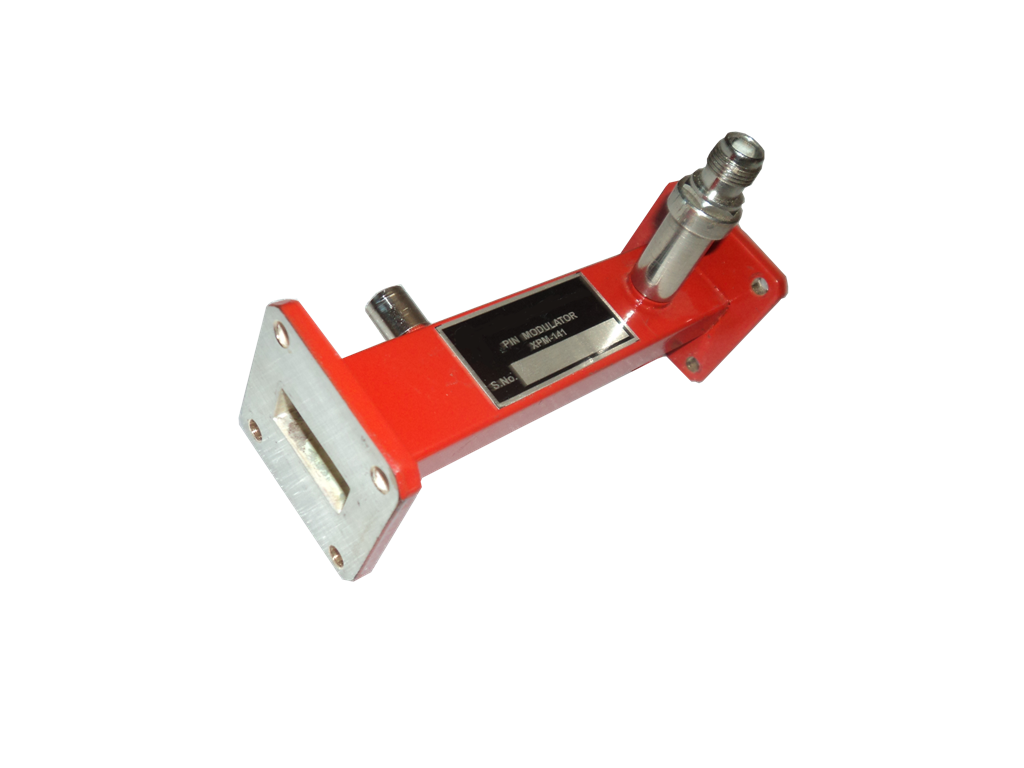
PIN Diode modulators offer an ideal way for amplitude and the pulse modulation of microwave signal through wide range of frequencies. These modulators utilize PIN Diode which are mounted across the waveguide line a R.F. isolated DC bias lead passing to an external TNC (F) Connectors.
| Model | Bias Voltage (Max) | Output Connectors | Waveguide |
|---|---|---|---|
| TL-141 | 10 volts | TNC (F) | WR-90 |
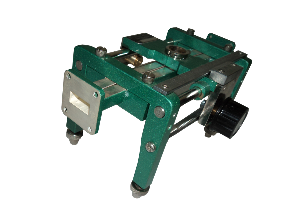
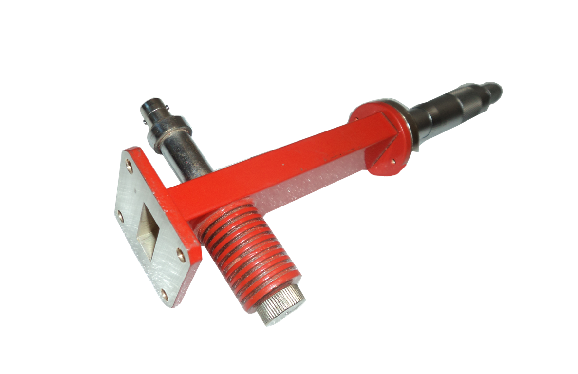
It is used for impedance matching in the transmission lines. A tuning screw attached with a micrometer along with the carriage helps in the impedance matching. Mismatches upto 20:1 can be tuned to a VSWR of less than 1.02 at any frequency in the waveguide band.
| Model | Band | Freq. Range(GHz) | Waveguide | VSWR |
|---|---|---|---|---|
| TL -162 | S | 2.60-3.95 | WR-284 | 1.02 |
| TL -162 | C | 3.95-5.85 | WR-229 | 1.02 |
| TL -162 | J | 5.85-8.20 | WR-137 | 1.02 |
| TL -162 | X | 8.20-12.40 | WR-90 | 1.02 |
| TL -162 | Ku | 12.40-18.00 | WR-62 | 1.02 |
| TL -162 | K | 18.00-26.50 | WR-42 | 1.02 |
E H Tuners provide a continent means of tuning out discontinuities in waveguide systems. Mismatches up to 20:1 can be tuned to a VSWR of less than 1.02 at any frequency in the waveguide band. 1.62 series provide EH Tuners with the micrometer to read the position of the plunger accurately while tuning process.
| Model | Band | Freq. Range(GHz) | Waveguide | VSWR |
|---|---|---|---|---|
| TL -162 | S | 2.60-3.95 | WR-284 | 1.02 |
| TL -162 | C | 3.95-5.85 | WR-229 | 1.02 |
| TL -162 | J | 5.85-8.20 | WR-137 | 1.02 |
| TL -162 | X | 8.20-12.40 | WR-90 | 1.02 |
This system consists of a transmission line (Waveguide), a travelling probe carriage and facility for attaching/detecting instruments. The slot made in the center of broad face do not radiate from any power of dominant mode. Slotted section is basically used to measure standing wave ratio (VSWR). The precession built probe carriage having centimeters scale with a vernier reading of 0.1mm least count is used to measure the position of the probe. Additionally slotted section can be used to measure impedance, reflection coefficient and the return loss.
| Model | Band | Freq. Range(GHz) | Waveguide | VSWR | Slope (db) |
|---|---|---|---|---|---|
| TL -148 | S | 2.60-3.95 | WR-284 | 1.02 | +/-0.2 |
| TL -148 | C | 3.95-5.85 | WR-229 | 1.02 | +/-0.2 |
| TL -148 | J | 5.85-8.20 | WR-137 | 1.02 | +/-0.2 |
| TL -148 | X | 8.20-12.40 | WR-90 | 1.02 | +/-0.2 |
| TL -148 | Ku | 12.40-18.00 | WR-62 | 1.02 | +/-0.2 |
| TL -148 | K | 18.00-26.50 | WR-42 | 1.02 | +/-0.2 |
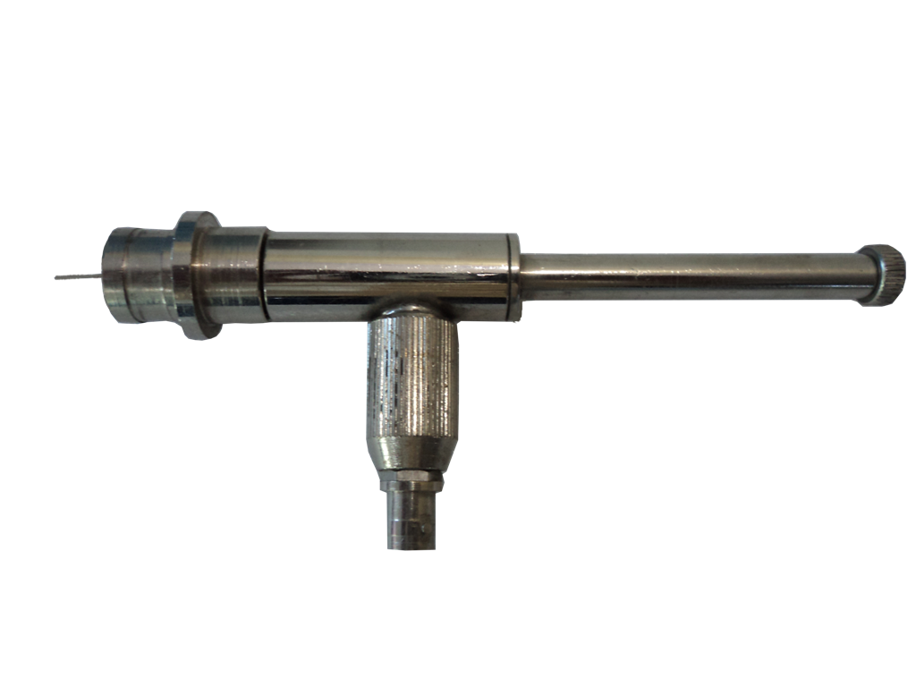
A tunable probe helps in detecting the low frequency square wave modulated microwave signal. It is made by the use of crystal diode mounted in the transmission line. The probe is connected to the crystal detector so that the output from the detector is proportional to the square of the input voltage at the position of the probe. As the position of the probe is moved along the waveguide slot it gives output proportional to the standing wave pattern inside the waveguide.
| Model | Band | Freq. Range(GHz) | Waveguide | Crystal Detector | Output Connectors |
|---|---|---|---|---|---|
| TL-153 | S | 2.60-3.95 | WR-284 | IN-21 | BNC (F) |
| TL -153 | C | 3.95-5.85 | WR-229 | IN-21 | BNC (F) |
| TL -153 | J | 5.85-8.20 | WR-137 | IN-23 | BNC (F) |
| TL -153 | X | 8.20-12.40 | WR-90 | IN-23 | BNC (F) |
| TL -153 | X | 12.40-18.00 | WR-62 | IN-23 | BNC (F) |
| TL -153 | K | 18.00-26.50 | WR-42 | IN-23 | BNC (F) |
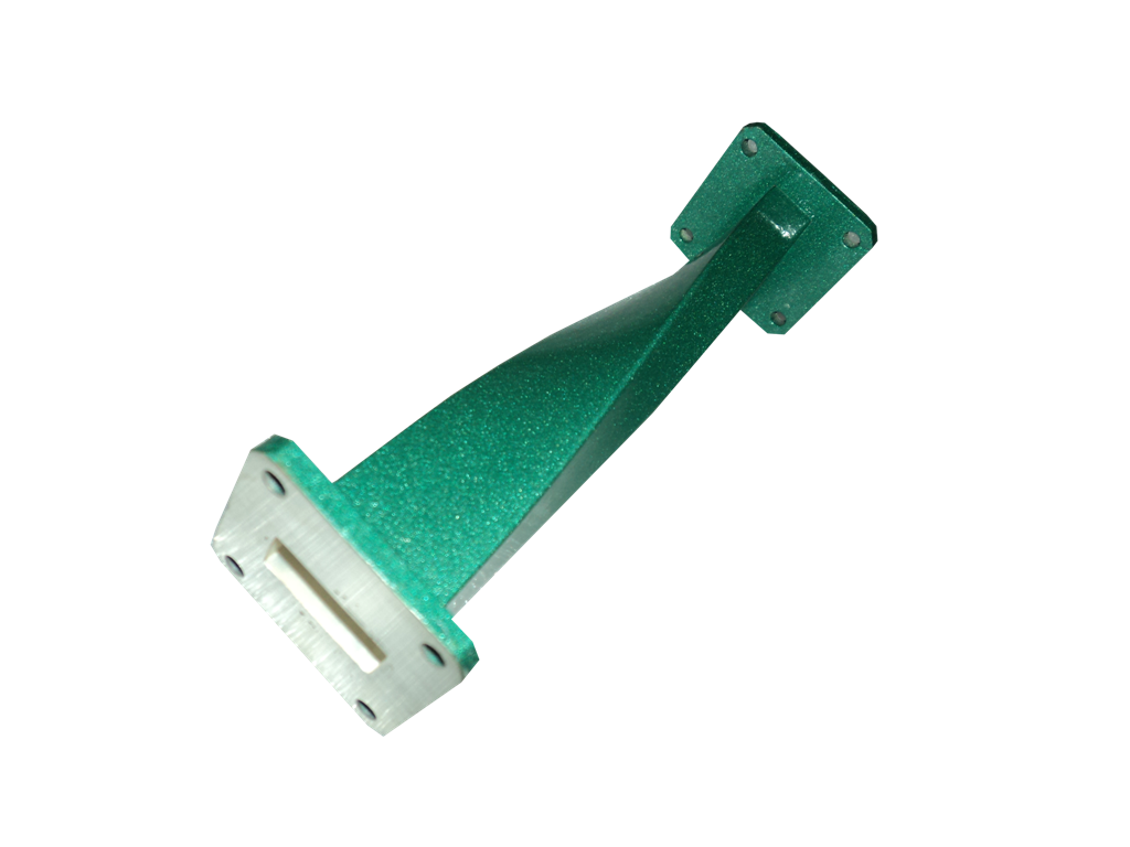
Twists are made from a section of the standard waveguide, which has been precisely twisted, maintaining the internal dimension of the waveguide. These are used to rotate the plane of polarization of waveguide transmission line.
| Model | Band | Freq. Range(GHz) | Waveguide | VSWR |
|---|---|---|---|---|
| TL-163 | S | 2.60-3.95 | WR-284 | 1.1 |
| TL -163 | C | 3.95-5.85 | WR-229 | 1.1 |
| TL -163 | J | 5.85-8.20 | WR-137 | 1.1 |
| TL -163 | X | 8.20-12.40 | WR-90 | 1.1 |
| TL -163 | Ku | 12.40-18.00 | WR-62 | 1.1 |
| TL -163 | K | 18.00-26.50 | WR-42 | 1.1 |
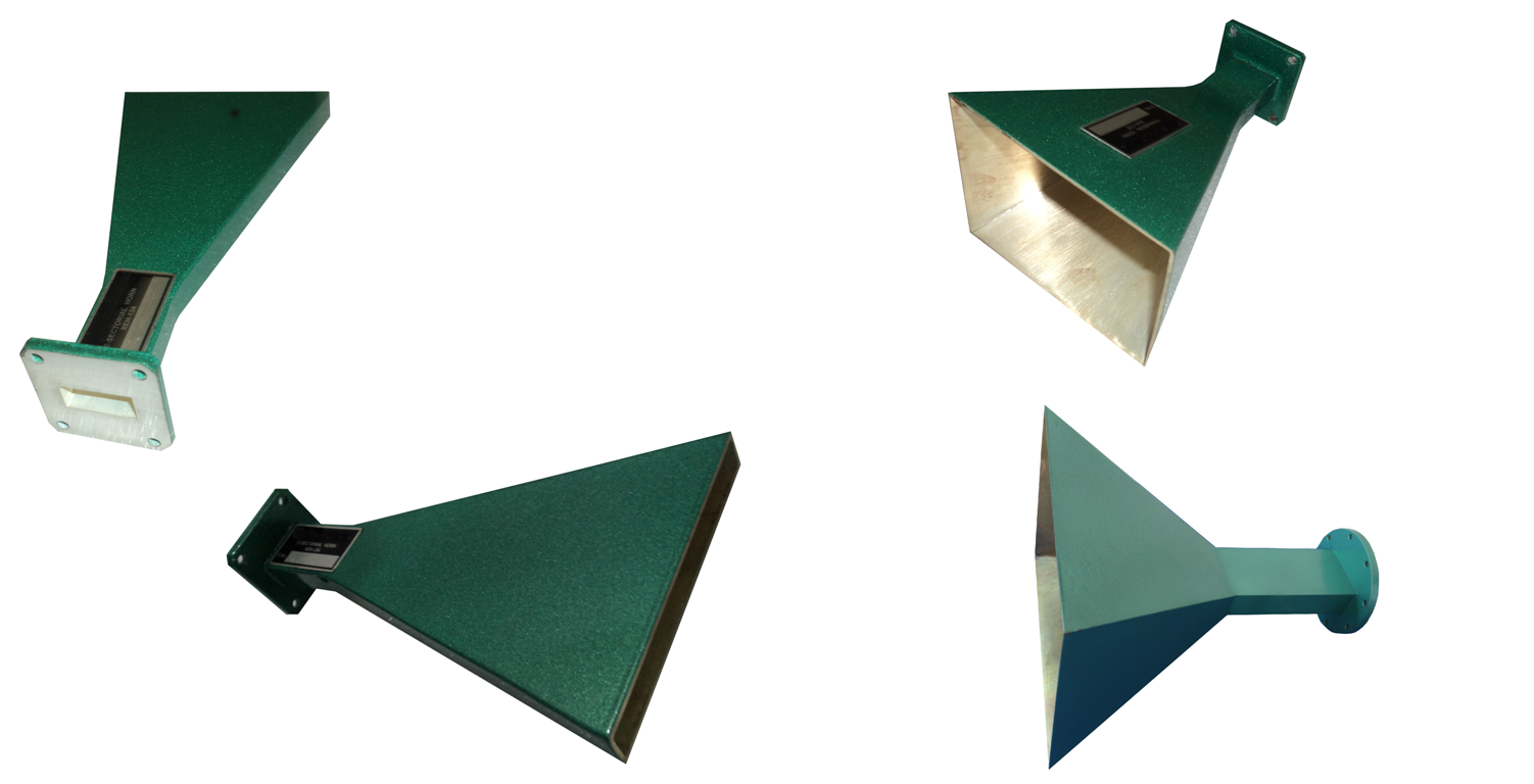
Horns are open ended Waveguide in which open end is flared so that it looks like horn. Commonly used horn antennas are pyramidal horn, E Sectorial, H Sectorial Horn and the pick up horns. These horns are used to determine the gain of the antenna under test by convectional substitution method and are also used as general purpose radiators. They are also used as reference sources in dual channel antenna test receivers and can be used as pick up horns for radiation monitoring.
| Model | Band | Freq. Range(GHz) | Waveguide | Coupling (dB) | Min Directivity (dB) |
|---|---|---|---|---|---|
| TL-133 | 2.6-3.95 | WR-284 | Pyramidal | 1.2 | 15 |
| TL -134 | 2.6-3.95 | WR-284 | Pick Up | 1.2 | 10 |
| TL -135 | 2.6-3.95 | WR-284 | E-Sectorial | 1.2 | 15 |
| TL -133 | 5.85-8.2 | WR-137 | Pyramidal | 1.2 | 16 |
| TL -134 | 5.85-8.2 | WR-137 | Pick Up | 1.2 | 10 |
| TL -135 | 5.85-8.2 | WR-137 | E-Sectorial | 1.2 | 15 |
| TL -136 | 5.85-8.2 | WR-137 | H-Sectorial | 1.2 | 15 |
| TL -133 | 8.2-12.4 | WR-90 | Pyramidal | 1.2 | 16 |
| TL -134 | 8.2-12.4 | WR-90 | Pick Up | 1.2 | 10 |
| TL -135 | 8.2-12.4 | WR-90 | E-Sectorial | 1.2 | 15 |
| TL -136 | 8.2-12.4 | WR-90 | H-Sectorial | 1.2 | 15 |
| TL -133 | 12.4-18.0 | WR-62 | Pyramidal | 1.2 | 15 |
| TL -134 | 12.4-18.0 | WR-62 | Pick Up | 1.2 | 10 |
| TL -135 | 12.4-18.0 | WR-62 | E-Sectorial | 1.2 | 15 |
| TL -136 | 12.4-18.0 | WR-62 | H-Sectorial | 1.2 | 15 |
| TL -133 | 18.0-26.5 | WR-42 | Pyramidal | 1.2 | 20 |
| TL -134 | 18.0-26.5 | WR-42 | Pick Up | 1.2 | 10 |
| TL -133 | 26.5-40.0 | WR-28 | Pyramidal | 1.2 | 15 |
A Waveguide is a hollow metallic tube of any cross section through which the transmission of the electromagnetic waves takes place by the successive reflections from the inner walls of the tube. The cross section of the waveguide is related to the frequency of the waves and is suitable for the transmission of signal in microwave frequency range. The rectangular waveguide is by far more important from a practical point of view, mainly because of the simplicity of the propagation phenomena involved.
| Model | Band | Freq. Range(GHz) | Inner Cross Section (mm) | Outer Cross Section (mm) |
|---|---|---|---|---|
| TL-284 | S | 2.60-3.95 | 72.14 X 34.04 | 76.20 X 38.01 |
| TL-229 | C | 3.95-5.85 | 58.17 X 29.083 | 61.42 X 32.33 |
| TL-137 | J | 5.85-8.20 | 34.85-15.799 | 38.10 X 19.05 |
| TL-90 | X | 8.20-12.40 | 22.860 X 10.160 | 25.40 X 12.70 |
| TL-62 | Ku | 12.40-18.00 | 15.799 X 7.899 | 12.70 X 6.35 |
| TL-42 | K | 18.00-26.50 | 10.688 X 4.318 | 12.70 X 6.35 |
| TL-28 | Ka | 26.4-40.1 | 7.112 X 3.556 | 9.14 X 5.59 |
PIN Diode modulators offer an ideal way for amplitude and the pulse modulation of microwave signal through wide range of frequencies. These modulators utilize PIN Diode which are mounted across the waveguide line a R.F. isolated DC bias lead passing to an external TNC (F) Connectors.
| Model | Bias Voltage (Max) | Output Connectors | Waveguide |
|---|---|---|---|
| TL-141 | 10 volts | TNC (F) | WR-90 |
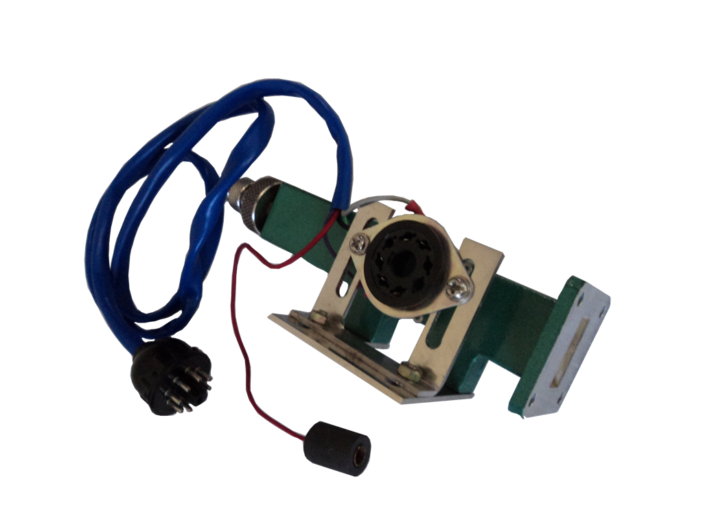
It is a waveguide of suitable length having octal base on the broad wall of the waveguide for mounting the klystron tube. It consists of movable short at one end of the waveguide to direct the microwave energy generated by the klystron tube. A small hole located exactly at the center of the broad wall of the waveguide is used to put the coupling pin of the tube as the electric field vector of EM energy is maximum at the center only. The maximum power transfer can be achieved by tuning of the movable plunger.
| Model | Band | Freq. Range (GHz) | Waveguide |
|---|---|---|---|
| TL-139 | S | 2.60-3.95 | WR-284 |
| TL | C | 3.95-5.85 | WR-229 |
| TL -139 | J | 5.85-8.20 | WR-137 |
| TL -139 | X | 8.20-12.40 | WR-90 |
| TL -139 | Ku | 12.40-18.00 | WR-62 |
These are basic measuring devices for the liquid and solid dielectric measurements respectively. These consist of cavity for keeping the sample to be measured and sample can be read by the meant of the micrometer fitted with the plunger.
| Model Liquid Cell | Model Solid Cell | Band | Freq. Range (GHz) | Waveguide |
|---|---|---|---|---|
| TL 117 | JSC 118 | J | 5.85-8.20 | WR-137 |
| TL 117 | XSC 118 | X | 8.20-12.40 | WR-90 |
In making measurement of waveguide component it is often desirable to absorb the power propagated down the waveguide. These are designed in such a way to absorb the maximum energy without having appreciable reflection assuring low VSWR.
| Model | Band | Freq. Range(GHz) | Waveguide | Type |
|---|---|---|---|---|
| TL-157 | S | 2.60-3.95 | WR-284 | Fixed |
| TL -157 | C | 3.95-5.85 | WR-229 | Fixed |
| TL -157 | J | 5.85-8.20 | WR-137 | Fixed |
| TL -157 | X | 8.20-12.40 | WR-90 | Fixed |
| TL -157 | Ku | 12.40-18.00 | WR-62 | Fixed |
| TL -157 | K | 18.00-26.50 | WR-42 | Fixed |
These are used to obtain a phase reference in the calibration of various experimental setup and are also used to vary the effective plane of reflection and therefore the phase of reflected wave. These are also useful in impedance measurement.
| Model Movable Short | Model Movable Precision Short | Band | Freq. Range(GHz) | Waveguide |
|---|---|---|---|---|
| TL-146 | SPS-145 | S | 2.60-3.95 | WR-284 |
| TL -146 | CPS-145 | C | 3.95-5.85 | WR-229 |
| TL -146 | JPS-145 | J | 5.85-8.20 | WR-137 |
| TL -146 | XPS-145 | X | 8.20-12.40 | WR-90 |
| TL -146 | KuPS-145 | Ku | 12.40-18.00 | WR-62 |
| TL -146 | KPS-145 | K | 18.00-26.50 | WR-42 |
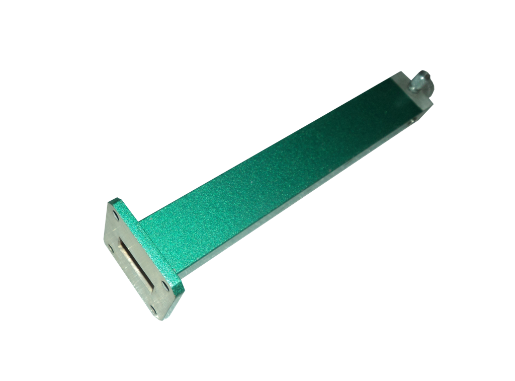
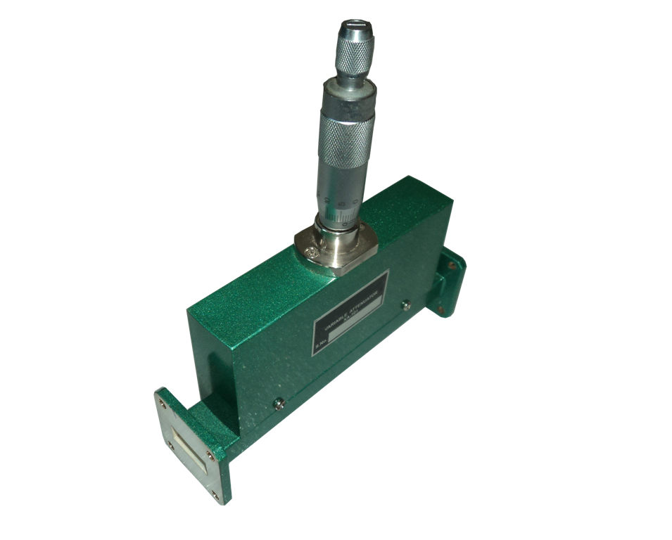
For perfect matching sometimes it is required that the microwave power in a waveguide be absorbed completely without any reflection and insensitive to frequency. For this attenuators are used. Attenuators are commonly used for measuring power gain or loss in dB’s for providing isolation between instruments, for reducing the power input to a particular stage to prevent overloading. Scientific Microwave offers fixed and variable attenuators to its customers.
Variable attenuatorsThese attenuators provide continuous attenuation power upto 20 dB.
| Model | Band | Freq. Range(GHz) | Waveguide | Attenuation(dB) | VSWR | Accuracy |
|---|---|---|---|---|---|---|
| TL 101 | S | 2.60-3.95 | WR-284 | 0-20 | 1.1 | +/-0.5 dB |
| TL 101 | C | 3.95-5.85 | WR-229 | 0-20 | 1.1 | +/-0.5 dB |
| TL 101 | J | 5.85-8.20 | WR-137 | 0-20 | 1.1 | +/-0.5 dB |
| TL 101 | X | 8.20-12.40 | WR-90 | 0-20 | 1.1 | +/-0.5 dB |
| TL 101 | Ku | 12.40-18.00 | WR-62 | 0-20 | 1.1 | +/-0.5 dB |
| TL 101 | K | 18.00-26.50 | WR-42 | 0-20 | 1.1 | +/-0.5 dB |
The attenuators provide fixed attenuation of 3, 6, 10, 20 dB
| Model | Band | Freq. Range(GHz) | Waveguide | Attenuation(dB) | VSWR | Accuracy |
|---|---|---|---|---|---|---|
| TL 102 | S | 2.60-3.95 | WR-284 | 3,6,10,20 | 1.08 | +/-0.5 dB |
| TL 102 | C | 3.95-5.85 | WR-229 | 3,6,10,20 | 1.08 | +/-0.5 dB |
| TL 102 | J | 5.85-8.20 | WR-137 | 3,6,10,20 | 1.08 | +/-0.5 dB |
| TL 101 | X | 8.20-12.40 | WR-90 | 3,6,10,20 | 1.1 | +/-0.5 dB |
| TL 102 | Ku | 12.40-18.00 | WR-62 | 3,6,10,20 | 1.08 | +/-0.5 dB |
| TL 102 | K | 18.00-26.50 | WR-42 | 3,6,10,20 | 1.08 | +/-0.5 dB |
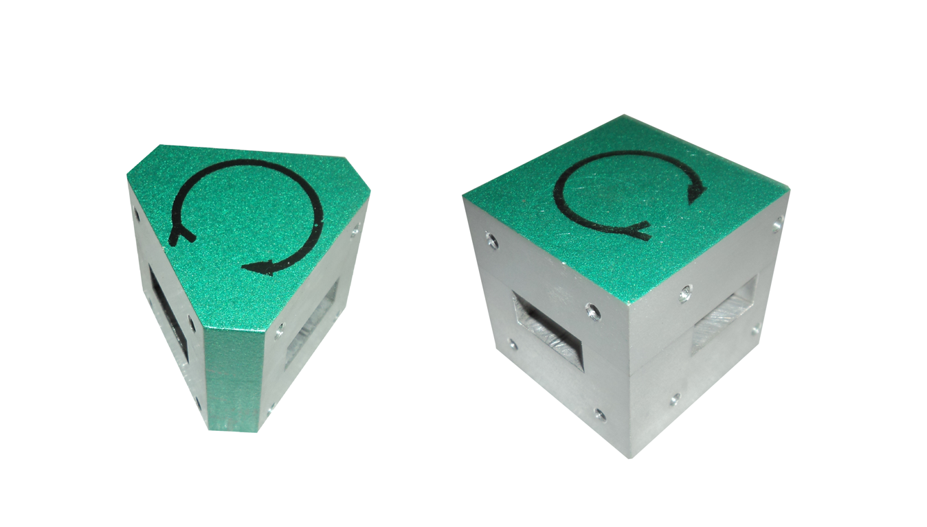
It is a multiport junction in which a wave can flow only from nth port to (n+1)th port in one direction. Although there is no restriction on the number of ports, the three port microwave circulator generally used.
| Model | Band | Freq. Range(GHz) | Waveguide | VSWR | Insertion Loss (mm.) | Isolation |
|---|---|---|---|---|---|---|
| TL 137 | J | 5.85-8.20 | WR-137 | 1.2 | 0.5dB | 20dB |
| TL 137 | X | 8.20-12.40 | WR-90 | 1.2 | 0.5dB | 20dB |
An Isolator is a non reciprocal transmission device that is used to isolate one component from reflections of other components in the transmission lines. An ideal isolator completely absorbs the power for propagation in one direction and provides lossless transmission in the opposite direction.
| Model | Band | Freq. Range(GHz) | Waveguide | VSWR | Insertion Loss (mm.) | Isolation |
|---|---|---|---|---|---|---|
| TL-137 | J | 5.85-8.20 | WR-137 | 1.2 | 0.5dB | 20dB |
| TL -137 | X | 8.20-12.40 | WR-90 | 1.2 | 0.5dB | 20dB |
This adaptor consists of a short section of standard waveguide with a probe transition coaxial mounted on broad wall. It transforms waveguide impedance into coaxial impedance Loq VSWR is maintained for optimum coupling.
| Model | Band | Freq. Range(GHz) | Waveguide | O/P Connector | VSWR |
|---|---|---|---|---|---|
| TL-100 | S | 2.60-3.95 | WR-284 | N-TYPE (F) | 1.3 |
| TL 100 | C | 3.95-5.85 | WR-229 | N-TYPE (F) | 1.3 |
| TL -100 | J | 5.85-8.20 | WR-137 | N-TYPE (F) | 1.3 |
| TL -100 | X | 8.20-12.40 | WR-90 | N-TYPE (F) | 1.3 |
| TL -100 | Ku | 12.40-18.00 | WR-62 | N-TYPE (F) | 1.3 |
| TL -100 | K | 18.00-26.50 | WR-42 | N-TYPE (F) | 1.3 |
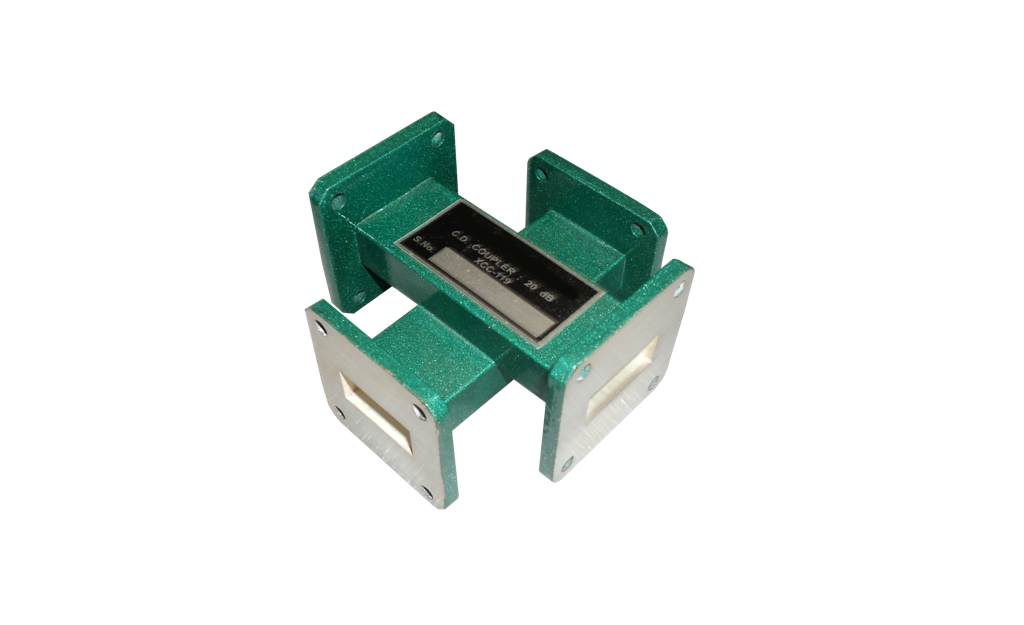
Cross Directional Couplers consist of two waveguide sectional joint at 90 degree with the coupling holes into the common broad wall. Each Model is furnished with a nominal mid band coupling value of 20 dB. On special order other coupling values can also be supplied.
| Model | Band | Freq. Range(GHz) | Waveguide | Coupling (dB) | Min Directivity (dB) |
|---|---|---|---|---|---|
| TL-119 | S | 2.60-3.95 | WR-284 | 20 | 25 |
| TL-119 | C | 3.95-5.85 | WR-229 | 20 | 25 |
| TL-119 | J | 5.85-8.20 | WR-137 | 20 | 25 |
| TL-119 | X | 8.20-12.40 | WR-90 | 20 | 25 |
| TL-119 | Ku | 12.40-18.00 | WR-62 | 20 | 25 |
| TL-119 | K | 18.00-26.50 | WR-42 | 20 | 25 |
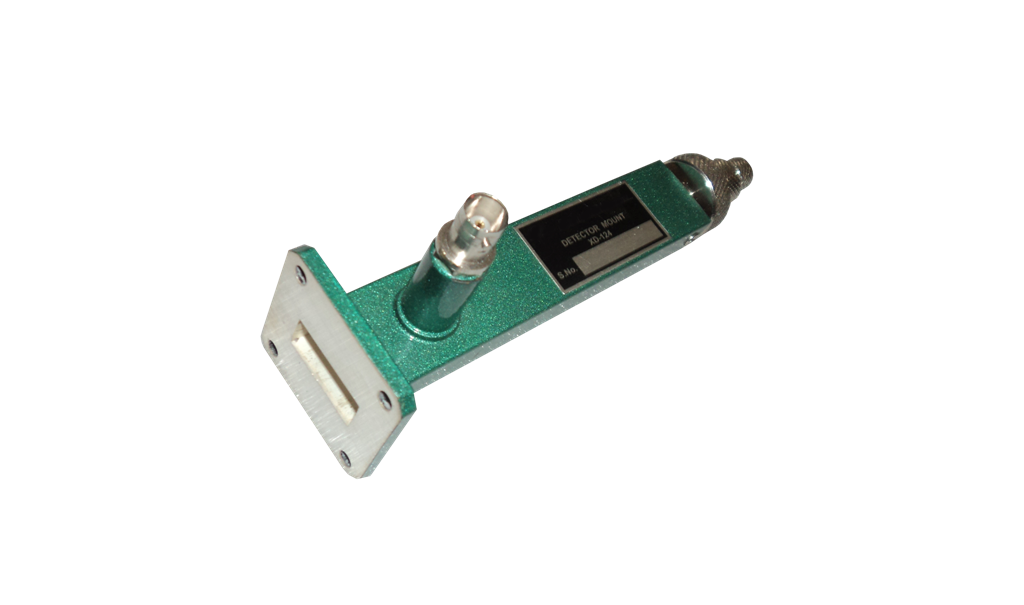
Detector Mount are used detect the low frequency signals with the help of the IN23 detector diode. The Detector Diode is mounted on the broad wall of the waveguide. A shorting plunger is used to tune the max power near the detector diode
| Model | Band | Freq. Range(GHz) | Waveguide | O/P Connector | Crystal Diode |
|---|---|---|---|---|---|
| TL-124 | S | 2.60-3.95 | WR-284 | BNC(F) | IN21 |
| TL -124 | C | 3.95-5.85 | WR-229 | BNC(F) | IN21 |
| TL -124 | J | 5.85-8.20 | WR-137 | BNC(F) | IN23 |
| TL -124 | X | 8.20-12.40 | WR-90 | BNC(F) | IN23 |
| TL -124 | Ku | 12.40-18.00 | WR-62 | BNC(F) | IN23 |
| TL -124 | K | 18.00-26.50 | WR-42 | BNC(F) | IN23 |
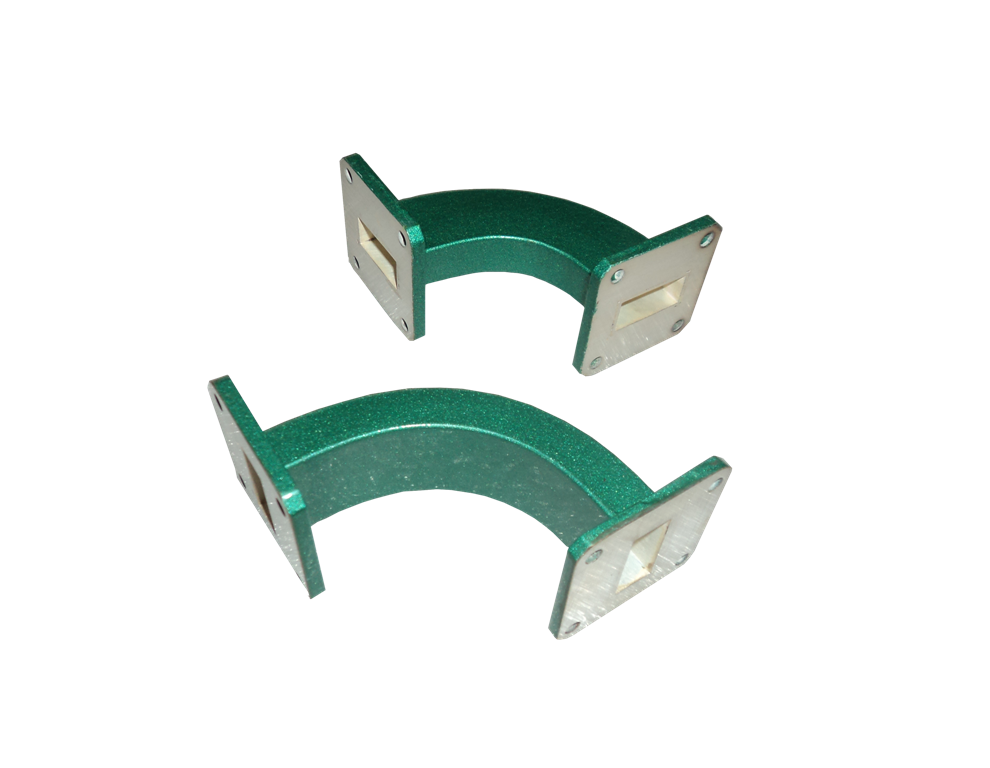
Bends are used to change the direction in a waveguide run. They are classified as E & H bends. A bend whose plane is parallel to the plane of the magnetic vector is called H bend while whose plane is parallel to the plane of the electric vector is called E bend. We have the facility of bending the waveguide at 300, 450, 600, 900 as per customer requirement.
| Model E-H | Band | Freq. Range(GHz) | Waveguide | VSWR |
|---|---|---|---|---|
| TL-101 | S | 2.60-3.95 | WR-284 | 1.06 |
| TL-101 | C | 3.95-5.85 | WR-229 | 1.06 |
| TL -101 | J | 5.85-8.20 | WR-137 | 1.06 |
| TL -101 | X | 8.20-12.40 | WR-90 | 1.06 |
| TL -101 | Ku | 12.40-18.00 | WR-62 | 1.06 |
| TL -101 | K | 18.00-26.50 | WR-42 | 1.06 |
An E-plane TEE is a waveguide tee in which the axis of side arm is parallel to the E field of the main guide. If the collinear arms are symmetric about the side arms, there are two arm characteristics. When wave are fed into the side arms, the wave appear in the collinear arms will be in opposite phase and in the same magnitude.
| Model | Band | Freq. Range(GHz) | Waveguide | VSWR |
|---|---|---|---|---|
| TL-154 | S | 2.60-3.95 | WR-284 | 1.2 |
| TL-154 | C | 3.95-5.85 | WR-229 | 1.2 |
| TL-154 | J | 5.85-8.20 | WR-137 | 1.2 |
| TL-154 | X | 8.20-12.40 | WR-90 | 1.2 |
| TL-154 | Ku | 12.40-18.00 | WR-62 | 1.2 |
| TL-154 | K | 18.00-26.50 | WR-42 | 1.2 |
An H-Plane TEE is a waveguide TEE in which the axis of its side arm is shunting the E field or parallel to the H field of the main guide and attaching the another waveguide.
| Model | Band | Freq. Range(GHz) | Waveguide | VSWR |
|---|---|---|---|---|
| TL-155 | S | 2.60-3.95 | WR-284 | 1.2 |
| TL-155 | C | 3.95-5.85 | WR-220 | 1.2 |
| TL-155 | J | 5.85-8.20 | WR-137 | 1.2 |
| TL-155 | X | 8.20-12.40 | WR-90 | 1.2 |
| TL-155 | Ku | 12.40-18.00 | WR-62 | 1.2 |
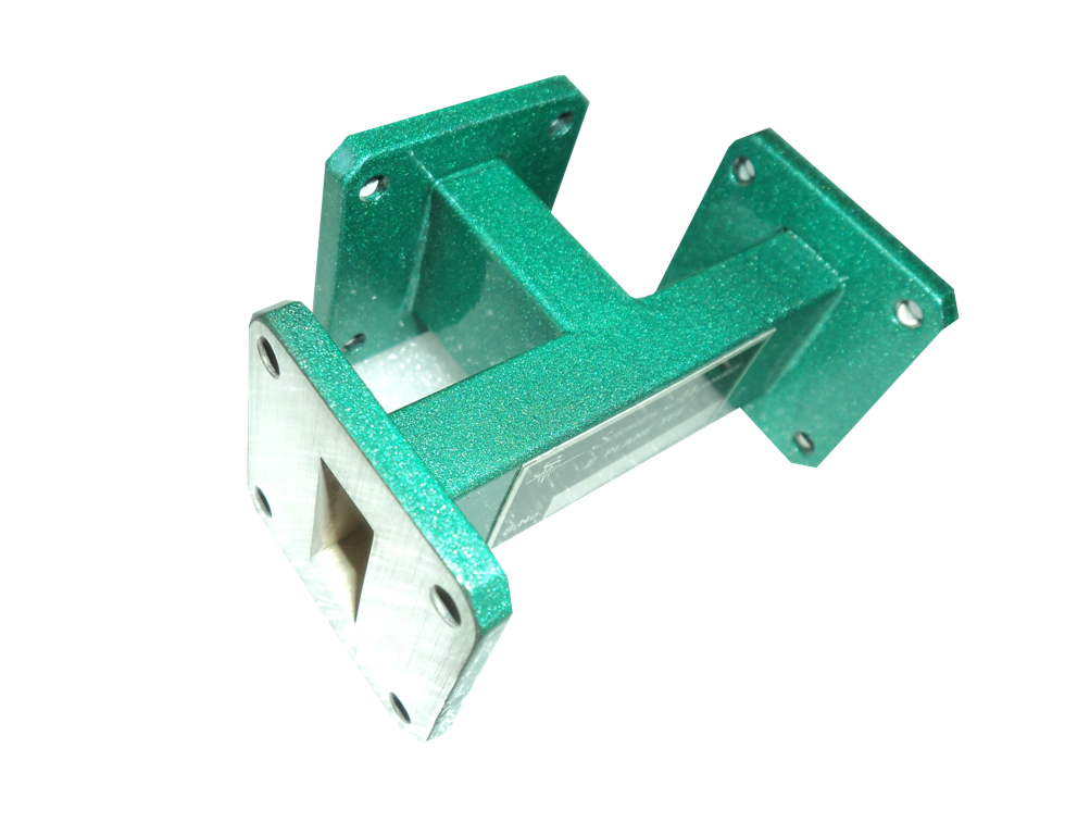
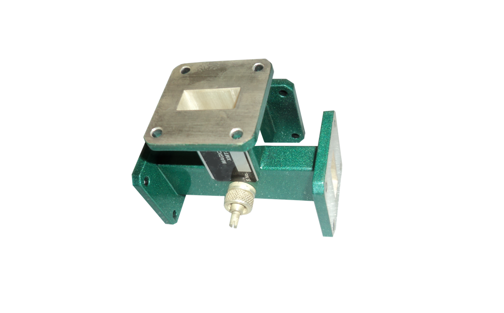
It is the combination of E-Plane TEE and H-Plane TEE. This four port waveguide junction combines the power dividing prosperities of E and H-Plane TEE.
| Model | Band | Freq. Range(GHz) | Waveguide | VSWR |
|---|---|---|---|---|
| TL-140 | S | 2.60-3.95 | WR-284 | 1.25 |
| TL-140 | C | 3.95-5.85 | WR-229 | 1.25 |
| TL-140 | J | 5.85-8.20 | WR-137 | 1.25 |
| TL-140 | X | 8.20-12.40 | WR-90 | 1.25 |
| TL-140 | Ku | 12.40-18.00 | WR-62 | 1.25 |
| TL-140 | K | 18.00-26.50 | WR-42 | 1.25 |
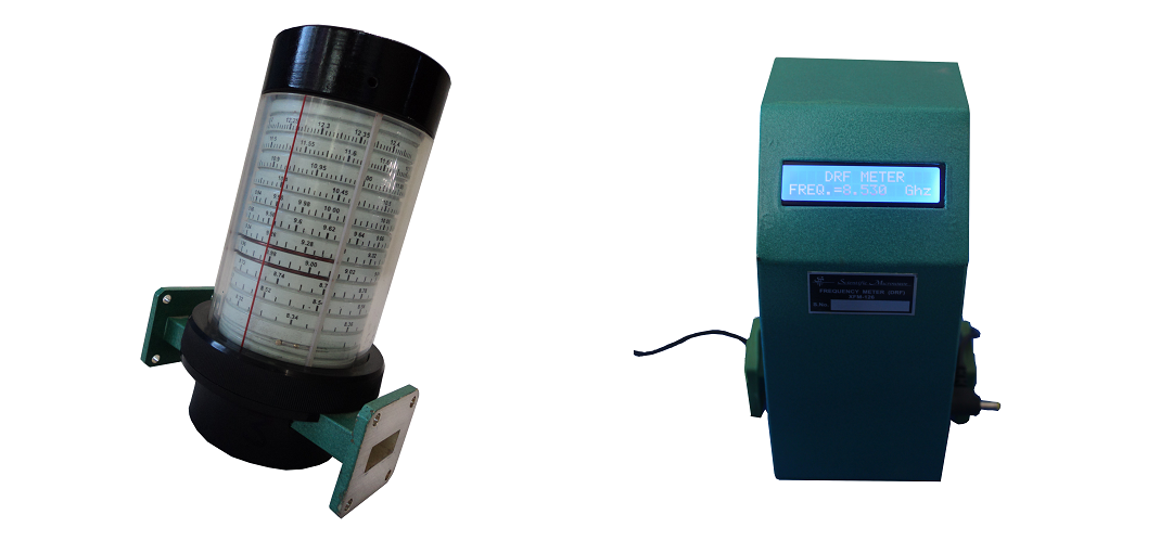
It is constructed from cylindrical cavity resonator with a variable short circuit termination. The shorting plunger is used to change the resonance frequency of the cavity by changing the cavity length. DRF measures the frequency directly. It is particularly useful when measuring frequency differences of small changes.
| Model | Band | Freq. Range(GHz) | Waveguide | Calibration | VSWR |
|---|---|---|---|---|---|
| TL-139 | X | 8.20-12.40 | WR-90 | +/-2 | 1.02 |
| TL-139 | Ku | 12.40-18.00 | WR-62 | +/-2 | 1.02 |
| TL-139 | K | 18.00-26.50 | WR-42 | +/-2 | 1.02 |
These frequency meters are intended for moderate accuracy application in microwave measurement and are usually best for this purpose. These permit full power flow down the transmission line except at the turned frequency. It consists of a cavity, plunger and the section of standard waveguide. The plunger ensures precise control of its position enabling frequency measurement with high accuracy.
| Model | Band | Freq. Range(GHz) | Waveguide | Calibration | VSWR |
|---|---|---|---|---|---|
| TL-125 | S | 2.60-3.95 | WR-284 | 10 | 1.03 |
| TL-125 | C | 3.95-5.85 | WR-229 | 10 | 1.03 |
| TL-125 | J | 5.85-8.20 | WR-137 | 10 | 1.03 |
| TL-125 | X | 8.20-12.40 | WR-90 | 10 | 1.03 |
| TL-125 | Ku | 12.40-18.00 | WR-62 | 10 | 1.03 |
| TL-125 | K | 18.00-26.50 | WR-42 | 10 | 1.03 |