Trusted Microwave Test Benches for Modern Engineering Laboratories
Precision-built RF and microwave laboratory systems backed by 20+ years of engineering expertise, OEM manufacturing, and dependable technical support.
Trusted by leading institutions across India IISc · IIT · BEL · DRDO · Manipal · M.S. Ramaiah · BMSCE · RVCE and many more..
Product Overview
Technilab Microwave Test Benches are complete laboratory systems designed to help students, educators, and researchers understand microwave engineering through practical experimentation.
Each system integrates carefully selected RF and microwave components into a structured learning platform, enabling users to perform experiments across microwave generation, transmission, measurement, wave propagation, antenna characteristics, and passive microwave devices.
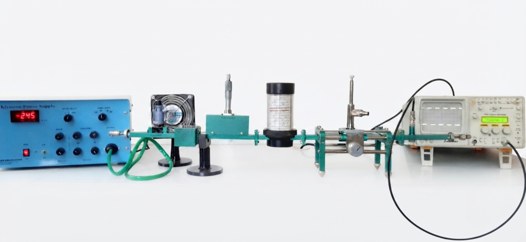
Every test bench is manufactured to deliver consistent performance, ease of operation, and long-term reliability, making it suitable for both academic laboratories and advanced research environments.

Why Choose Our Microwave Test Benches
Complete Lab Solution
Industry-Standard Experiments
OEM Manufactured
Technical & After-Sales Support
KLYSTRON POWER SUPPLY
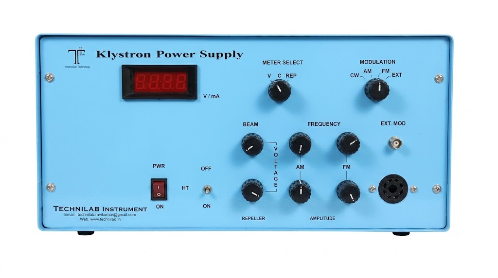
Overview
The Technilab Klystron Power Supply provides regulated beam, repeller, and heater voltages required for Reflex Klystron operation. Built-in square wave and sawtooth modulation enable accurate microwave experiments, making it an essential component of microwave laboratory test benches.
KLYSTRON POWER SUPPLY SPECIFICATION
| Model | TLKPS-204 |
| Beam Supply | |
| Voltage Range | 200 – 450 V Continuously Variable |
| Current | 50mA Max |
| Regulation | Better Than 0.5% for ±10% variation in mains Supply Voltage |
| Ripple | Less than 5mV rms |
| Repeller Supply | |
| Voltage Range | -10V to -270V DC continuously Variable |
| Regulation | 0.25% for ±10% variation |
| Heater Supply | 6.3V DC (regulated) |
| Modulation | |
| Square Wave | Freq.: 500 Hz-2000Hz Max. Amp. + 110 Volt peak to peak Amplitude and frequency continuously variable |
| Sawtooth | Freq.: 50Hz – 150Hz Amplitude – 60 V Max: peak to peak Amplitude and frequency continuously variable |
| Operation Voltage | 230 V ± 10%, 50 Hz. A.C. |
GUNN POWER SUPPLY

Model : TLGS-205
Overview
Provides a stable and regulated DC supply for Gunn Oscillator operation, ensuring consistent microwave signal generation for RF and microwave laboratory experiments.
GUNN POWER SUPPLY SPECIFICATION
| Voltage Range | 0 to 12 Volts Variable |
| Current | 1 Amp. Max |
| Regulation | 0.2% for ± 10% variation in the Mains Supply Voltage |
| Ripple | 1M V rms |
| Modulation Frequency | 1KHz ± 10% (900-1100Hz) |
| Output Connector | BNC (F) for Gunn Oscillator & TNC (F) for Pin Modulator |
VOLTAGE STANDING WAVE RATION (VSWR) METERS
Overview
A precision measurement instrument used to detect and measure standing wave patterns, enabling accurate analysis of microwave power, impedance matching, and transmission characteristics.
Specifications of VSWR, Meter Model : TLSW 214
| Sensitivity | 0.2µ V at a 200 Ohms input impedance for full scale deflection. |
| Noise Level | At least 5 dB below full scale at rated sensitivity and maximum band width With input terminated in 100 ohms and 500 ohms for crystal low and high respectively. |
| Calibration | Square law, meter indicates SWR, dB. |
| Range | 70 db, Input attenuator provides 60dB in 10 dB steps, accuracy ± 0.2 dB per 10 dB steps Maximum Cummulative error ± 0.5dB. |
| Scales Selector | “Normal”, “Expand” and -5 dB Frequency |
| Meter Scale | SWR1-4, SWR 3-10, expand SWR 1 1-3, dB 0-10, expand dB 0-2 |
| Gain Control | Adjusts the reference level, variable range 0-10 db approx. |
| Input | “Bolo” bias provided for 4.3 mA low current bolo meters. “Crystal” 200 ohms for low impedance crystal rectifier & 200 K ohms high impedance crystal rectifier as null detector |
| Recorder Output | Socket provided for recording having 1 V for full scale deflection. Internal resistance of 1000 ohms or less |
| A/C Output | BNC Connector for amplified output. |
| Input Connector | BNC (F) |
| Frequency | 1000Hz ± 10% |
| Power | 230 volts A.C. ± 10%, 50 Hz, mains supply. |
Specifications of VSWR, Meter Model : TLSW 215
| Sensitivity | 0.2µ V for full scale deflection at maximum bandwidth on low impedance crystal input. |
| Noise Level | At least 5 dB below full scale at rated sensitivity and maximum band width With input terminated in 100 ohms or 500 ohms for crystal low and high respectively. |
| Range | 70 db, in 10 dB and 2 dB steps. |
| Range Accuracy | 0.1 dB per 10dB steps |
| Input | Unbiased low and high impedance crystal, biased crystal (200Ω 200K) Low and high current bolometers (4.5 & 8.7 mA) (200 ohm) |
| Meter Scale | SWR1-4, SWR 3-10, expand SWR 1 1-3, dB 0-10, expand dB 0-2 |
| Gain Control | Adjusts the reference level, variable range 0-10 db approx. |
| Input | “Bolo” bias provided for 4.3 mA low current bolo meters. “Crystal” 200 ohms for low impedance crystal rectifier & 200 K ohms high impedance crystal rectifier as null detector |
| Input Frequency | 1 KHz adjustable ± 10% by front panel control. |
| Band Width | Variable 25 Hz to 110 Hz. |
| Meter Scale | SWR1-4, SWR 3-10, expand SWR 1 1-3, dB 0-10, expand dB 0-2 |
| Gain Control | Adjusts the reference level, variable range 0-10 db approx. |
| Recorder Output | 0-1V DC, output connector, Banana Socket. |
| Amplifier output | 0-0.3 Vrms into atleast 10K ohms, output connector BNC (F) |
| Input Connector | BNC (F) |
| Power | 230 volts A.C. ± 10%, 50 Hz, mains supply. |
Model No TL 001 Microwave Test bench X BAND : FREQUENCY : 8.2 TO 12.4 GHz EXPERIMENTS

Overview
An entry-level X-Band microwave laboratory system designed for fundamental RF and microwave experiments, making it ideal for introductory engineering laboratories.
Specifications
| Sl.No | Microwave Signal Source – VCO Based | QTY |
|---|---|---|
| 1 | Microwave Signal Source – VCO Based | 1 |
| 2 | R F Power Meter | 1 |
| 3 | Micro strip Resonator | 1 |
| 4 | Micro Strip Power Divider | 1 |
| 5 | Micro strip Branch line coupler | 1 |
| 6 | Micro strip Paraller line coupler | 1 |
| 7 | RF Detector | 1 |
| 8 | SMA Matched Termination | 100 |
| 9 | SMA – BNC Cable | 1 |
| 10 | SMA – SMA RF Cable (RG 188) – 1 meter | 100 |
| 11 | SMA – SMA RF Cable Short Length | 1 |
| 12 | 6 dB Attenuator | 2 |
Model No TL 002 Microwave Test bench (Microwave Trainer Kit – GUNN DIODE Source Based)

Overview
A comprehensive microwave trainer kit featuring a Gunn Diode source, designed for practical learning of microwave generation, transmission, and measurement techniques.
Specifications
| Sl.No | Gunn Power Supply Power Supply – Solid State | QTY |
|---|---|---|
| 1 | Gunn Oscillator | 1 |
| 2 | Pin Modulator | 1 |
| 3 | Isolator | 1 |
| 4 | Detector Mount | 1 |
| 5 | Direct Reading Frequency Meter | 1 |
| 6 | Variable Attenuator | 1 |
| 7 | Slotted Section | 1 |
| 8 | Tunable Probe | 1 |
| 9 | Screws And Nuts | 100 |
| 10 | Cooling Fan | 1 |
| 11 | BNC – BNC Cable | 2 |
| 12 | Waveguide Stand | 2 |
| 13 | Matched Termination | 1 |
| 14 | VSWR Meter | 1 |
| 15 | Shorting Plate | 1 |
| 16 | VSWR Meter | 2 |
| 17 | Variable Attenuator | 1 |
| 18 | VSWR MeteTNC – TNC Cable | 2 |
Model No TL 003 Microwave Test bench (Microwave Trainer Kit – Klystron Source Based)
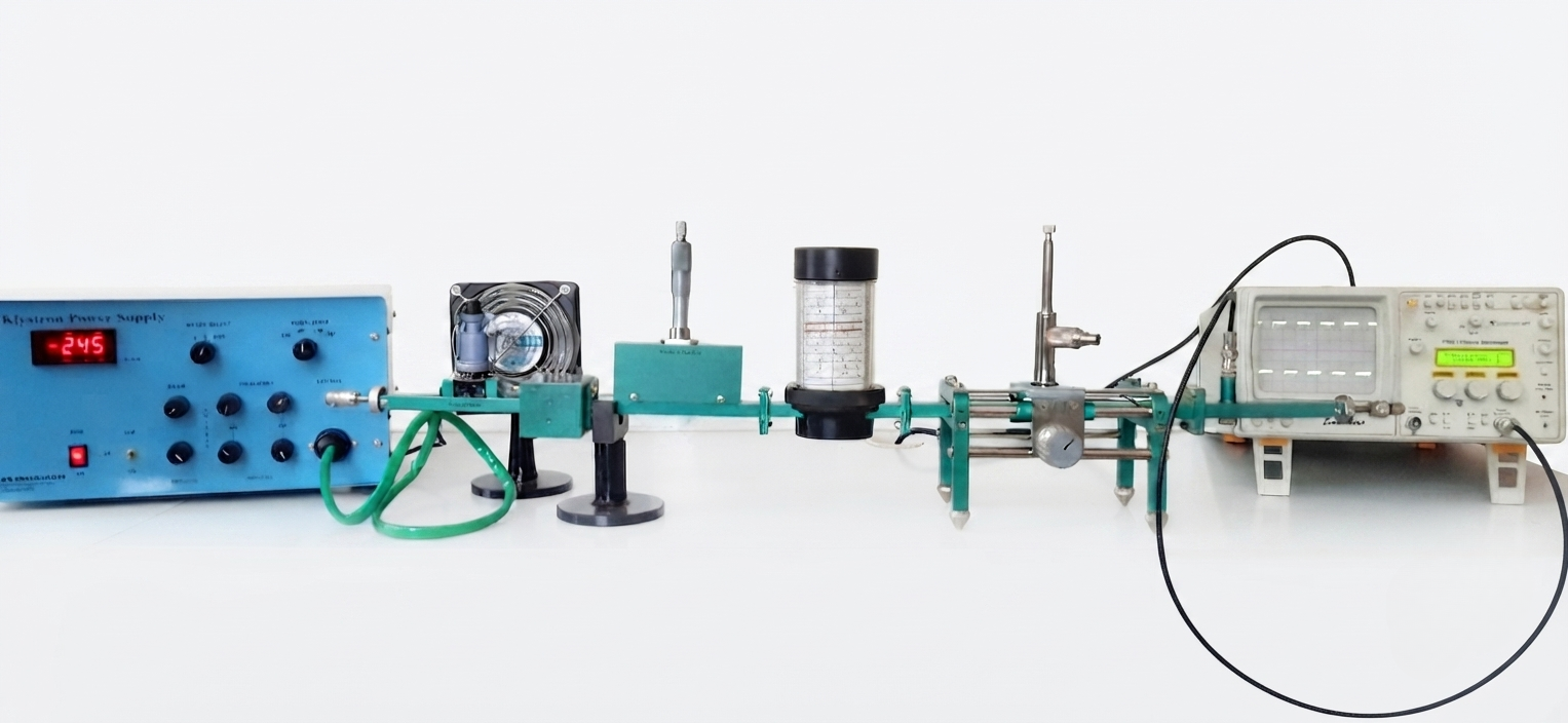
Overview
A Klystron-based microwave laboratory system that enables detailed study of microwave engineering principles through a wide range of practical experiments.
Specifications
| Sl.No | Gunn Power Supply Power Supply – Solid State | QTY |
|---|---|---|
| 1 | Gunn Oscillator | 1 |
| 2 | Pin Modulator | 1 |
| 3 | Isolator | 1 |
| 4 | Detector Mount | 1 |
| 5 | Direct Reading Frequency Meter | 1 |
| 6 | Variable Attenuator | 1 |
| 7 | Slotted Section | 1 |
| 8 | Tunable Probe | 1 |
| 9 | Screws And Nuts | 100 |
| 10 | Cooling Fan | 1 |
| 11 | BNC – BNC Cable | 2 |
| 12 | Waveguide Stand | 2 |
| 13 | Matched Termination | 1 |
| 14 | VSWR Meter | 1 |
| 15 | Shorting Plate | 1 |
| 16 | VSWR Meter | 2 |
| 17 | Variable Attenuator | 1 |
| 18 | VSWR MeteTNC – TNC Cable | 2 |
Model No TL 004 Microwave Test bench (Microwave Trainer Kit – Klystron Source Based) X Band : Frequency Range : 8.2 to 12.4 Ghz Power output > 25 mW
Overview
An advanced X-Band microwave training system with enhanced experiment capabilities, delivering reliable performance for engineering education and research applications
Specifications
| Model | TLKPS-204 |
| Beam Supply | |
| Voltage Range | 200 – 450 V Continuously Variable |
| Current | 50mA Max |
| Regulation | Better Than 0.5% for ±10% variation in mains Supply Voltage |
| Ripple | Less than 5mV rms |
| Repeller Supply | |
| Voltage Range | -10V to -270V DC continuously Variable |
| Regulation | 0.25% for ±10% variation |
| Heater Supply | 6.3V DC (regulated) |
Model No TL 005 Microwave Test bench (Microwave Trainer Kit – Klystron Source Based) X Band : Frequency Range : 8.2 to 12.4 Ghz Power output > 25 mW
Overview
Our most comprehensive microwave laboratory platform, designed for advanced RF experimentation, postgraduate studies, and research laboratories requiring expanded capabilities.
Specifications
| Model | TLKPS-204 |
| Beam Supply | |
| Voltage Range | 200 – 450 V Continuously Variable |
| Current | 50mA Max |
| Regulation | Better Than 0.5% for ±10% variation in mains Supply Voltage |
| Ripple | Less than 5mV rms |
| Repeller Supply | |
| Voltage Range | -10V to -270V DC continuously Variable |
| Regulation | 0.25% for ±10% variation |
| Heater Supply | 6.3V DC (regulated) |
Multi-Hole Directional Coupler
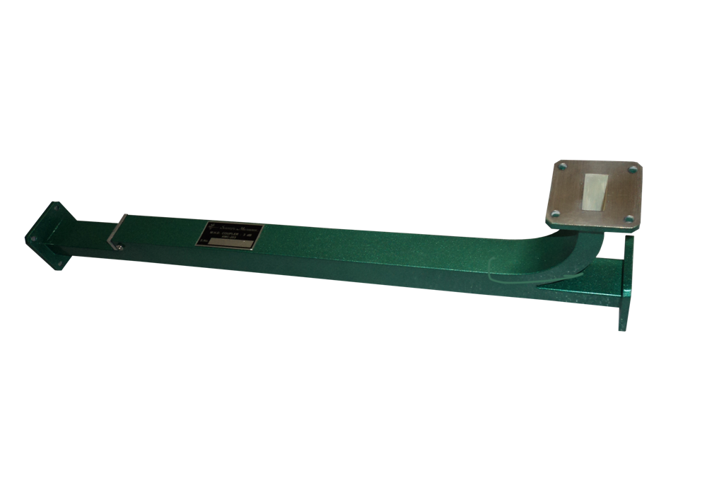
Overview
A precision waveguide component used to sample microwave power with minimal signal loss, enabling accurate power measurement and signal monitoring.
Specifications
| Model | Band | Freq. Range (GHz) | Waveguide | O/P Connector | Crystal Diode |
|---|---|---|---|---|---|
| TL-124 | S | 2.60 - 3.95 | WR-284 | BNC(F) | IN21 |
Phase Shifters
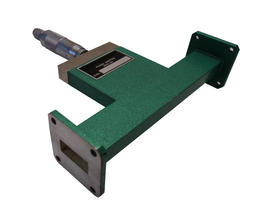
Designed to introduce controlled phase variations in microwave signals, making them essential for phase measurement and wave propagation experiments.
Specifications
| Model | Band | Freq. Range (GHz) | Waveguide | O/P Connector | Crystal Diode |
|---|---|---|---|---|---|
| TL-124 | S | 2.60 - 3.95 | WR-284 | BNC(F) | IN21 |
| TL-124 | C | 3.95 - 5.85 | WR-229 | BNC(F) | IN21 |
| TL-124 | J | 5.85 - 8.20 | WR-137 | BNC(F) | IN23 |
| TL-124 | X | 8.20 - 12.40 | WR-90 | BNC(F) | IN23 |
| TL-124 | Ku | 12.40 - 18.00 | WR-62 | BNC(F) | IN23 |
| TL-124 | K | 18.00 - 26.50 | WR-42 | BNC(F) | IN23 |
Pin Modulator

Specifications
| Model | Band | Freq. Range (GHz) | Waveguide | O/P Connector | Crystal Diode |
|---|---|---|---|---|---|
| TL-124 | S | 2.60 - 3.95 | WR-284 | BNC(F) | IN21 |
| TL-124 | C | 3.95 - 5.85 | WR-229 | BNC(F) | IN21 |
| TL-124 | J | 5.85 - 8.20 | WR-137 | BNC(F) | IN23 |
| TL-124 | X | 8.20 - 12.40 | WR-90 | BNC(F) | IN23 |
| TL-124 | Ku | 12.40 - 18.00 | WR-62 | BNC(F) | IN23 |
| TL-124 | K | 18.00 - 26.50 | WR-42 | BNC(F) | IN23 |
Slide Screw Tuners

Specifications
| Model | Band | Freq. Range (GHz) | Waveguide | O/P Connector | Crystal Diode |
|---|---|---|---|---|---|
| TL-124 | S | 2.60 - 3.95 | WR-284 | BNC(F) | IN21 |
| TL-124 | C | 3.95 - 5.85 | WR-229 | BNC(F) | IN21 |
| TL-124 | J | 5.85 - 8.20 | WR-137 | BNC(F) | IN23 |
| TL-124 | X | 8.20 - 12.40 | WR-90 | BNC(F) | IN23 |
| TL-124 | Ku | 12.40 - 18.00 | WR-62 | BNC(F) | IN23 |
| TL-124 | K | 18.00 - 26.50 | WR-42 | BNC(F) | IN23 |
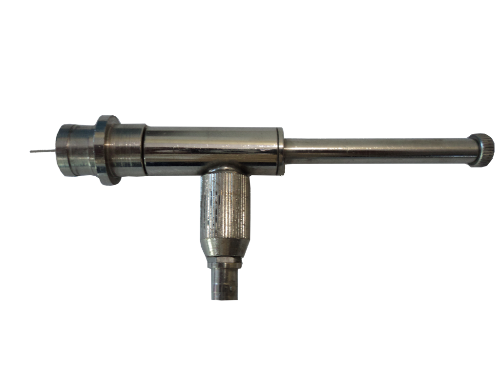
Tunable Probe
Specifications
| Model | Band | Freq. Range (GHz) | Waveguide | O/P Connector | Crystal Diode |
|---|---|---|---|---|---|
| TL-124 | S | 2.60 - 3.95 | WR-284 | BNC(F) | IN21 |
| TL-124 | C | 3.95 - 5.85 | WR-229 | BNC(F) | IN21 |
| TL-124 | J | 5.85 - 8.20 | WR-137 | BNC(F) | IN23 |
| TL-124 | X | 8.20 - 12.40 | WR-90 | BNC(F) | IN23 |
| TL-124 | Ku | 12.40 - 18.00 | WR-62 | BNC(F) | IN23 |
| TL-124 | K | 18.00 - 26.50 | WR-42 | BNC(F) | IN23 |
E-H Tuners
Specifications
| Model | Band | Freq. Range (GHz) | Waveguide | O/P Connector | Crystal Diode |
|---|---|---|---|---|---|
| TL-124 | S | 2.60 - 3.95 | WR-284 | BNC(F) | IN21 |
| TL-124 | C | 3.95 - 5.85 | WR-229 | BNC(F) | IN21 |
| TL-124 | J | 5.85 - 8.20 | WR-137 | BNC(F) | IN23 |
| TL-124 | X | 8.20 - 12.40 | WR-90 | BNC(F) | IN23 |
| TL-124 | Ku | 12.40 - 18.00 | WR-62 | BNC(F) | IN23 |
| TL-124 | K | 18.00 - 26.50 | WR-42 | BNC(F) | IN23 |
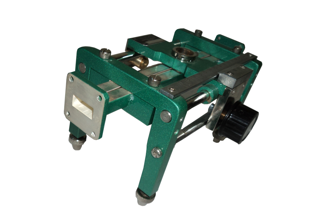
Slotted Section With Probe Carriage
Specifications
| Model | Band | Freq. Range (GHz) | Waveguide | O/P Connector | Crystal Diode |
|---|---|---|---|---|---|
| TL-124 | S | 2.60 - 3.95 | WR-284 | BNC(F) | IN21 |
| TL-124 | C | 3.95 - 5.85 | WR-229 | BNC(F) | IN21 |
| TL-124 | J | 5.85 - 8.20 | WR-137 | BNC(F) | IN23 |
| TL-124 | X | 8.20 - 12.40 | WR-90 | BNC(F) | IN23 |
| TL-124 | Ku | 12.40 - 18.00 | WR-62 | BNC(F) | IN23 |
| TL-124 | K | 18.00 - 26.50 | WR-42 | BNC(F) | IN23 |
Twists

Specifications
| Model | Band | Freq. Range (GHz) | Waveguide | O/P Connector | Crystal Diode |
|---|---|---|---|---|---|
| TL-124 | S | 2.60 - 3.95 | WR-284 | BNC(F) | IN21 |
| TL-124 | C | 3.95 - 5.85 | WR-229 | BNC(F) | IN21 |
| TL-124 | J | 5.85 - 8.20 | WR-137 | BNC(F) | IN23 |
| TL-124 | X | 8.20 - 12.40 | WR-90 | BNC(F) | IN23 |
| TL-124 | Ku | 12.40 - 18.00 | WR-62 | BNC(F) | IN23 |
| TL-124 | K | 18.00 - 26.50 | WR-42 | BNC(F) | IN23 |
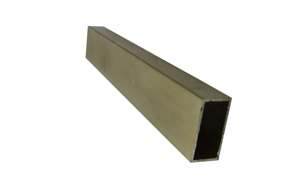
Waveguide Passive & Active Components
Specifications
| Model | Band | Freq. Range (GHz) | Waveguide | O/P Connector | Crystal Diode |
|---|---|---|---|---|---|
| TL-124 | S | 2.60 - 3.95 | WR-284 | BNC(F) | IN21 |
| TL-124 | C | 3.95 - 5.85 | WR-229 | BNC(F) | IN21 |
| TL-124 | J | 5.85 - 8.20 | WR-137 | BNC(F) | IN23 |
| TL-124 | X | 8.20 - 12.40 | WR-90 | BNC(F) | IN23 |
| TL-124 | Ku | 12.40 - 18.00 | WR-62 | BNC(F) | IN23 |
| TL-124 | K | 18.00 - 26.50 | WR-42 | BNC(F) | IN23 |
Waveguide Horn Antennas

Specifications
| Model | Band | Freq. Range (GHz) | Waveguide | O/P Connector | Crystal Diode |
|---|---|---|---|---|---|
| TL-124 | S | 2.60 - 3.95 | WR-284 | BNC(F) | IN21 |
| TL-124 | C | 3.95 - 5.85 | WR-229 | BNC(F) | IN21 |
| TL-124 | J | 5.85 - 8.20 | WR-137 | BNC(F) | IN23 |
| TL-124 | X | 8.20 - 12.40 | WR-90 | BNC(F) | IN23 |
| TL-124 | Ku | 12.40 - 18.00 | WR-62 | BNC(F) | IN23 |
| TL-124 | K | 18.00 - 26.50 | WR-42 | BNC(F) | IN23 |
GUNN Oscillator
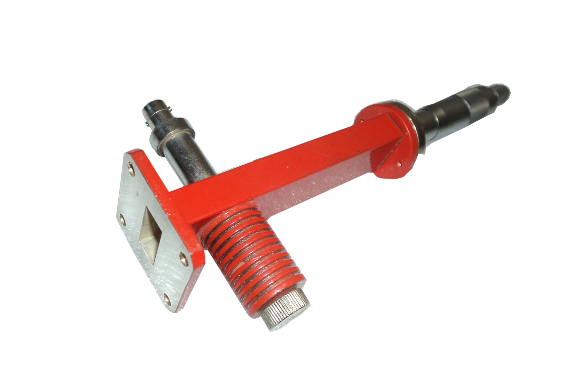
A microwave source that generates stable continuous-wave signals using Gunn diode technology, ideal for practical RF and microwave laboratory applications.
Specifications
| Model | Band | Freq. Range (GHz) | Waveguide | O/P Connector | Crystal Diode |
|---|---|---|---|---|---|
| TL-124 | S | 2.60 - 3.95 | WR-284 | BNC(F) | IN21 |
Klystron Mount
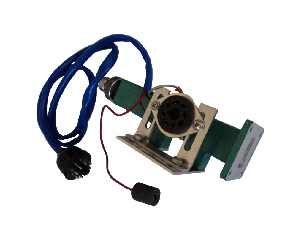
A precision mounting assembly designed to securely house Reflex Klystron Tubes while ensuring efficient microwave signal generation.
Specifications
| Model | Band | Freq. Range (GHz) | Waveguide | O/P Connector | Crystal Diode |
|---|---|---|---|---|---|
| TL-124 | S | 2.60 - 3.95 | WR-284 | BNC(F) | IN21 |
| TL-124 | C | 3.95 - 5.85 | WR-229 | BNC(F) | IN21 |
| TL-124 | J | 5.85 - 8.20 | WR-137 | BNC(F) | IN23 |
| TL-124 | X | 8.20 - 12.40 | WR-90 | BNC(F) | IN23 |
| TL-124 | Ku | 12.40 - 18.00 | WR-62 | BNC(F) | IN23 |
| TL-124 | K | 18.00 - 26.50 | WR-42 | BNC(F) | IN23 |
Liquid/Solid Dielectric Cell
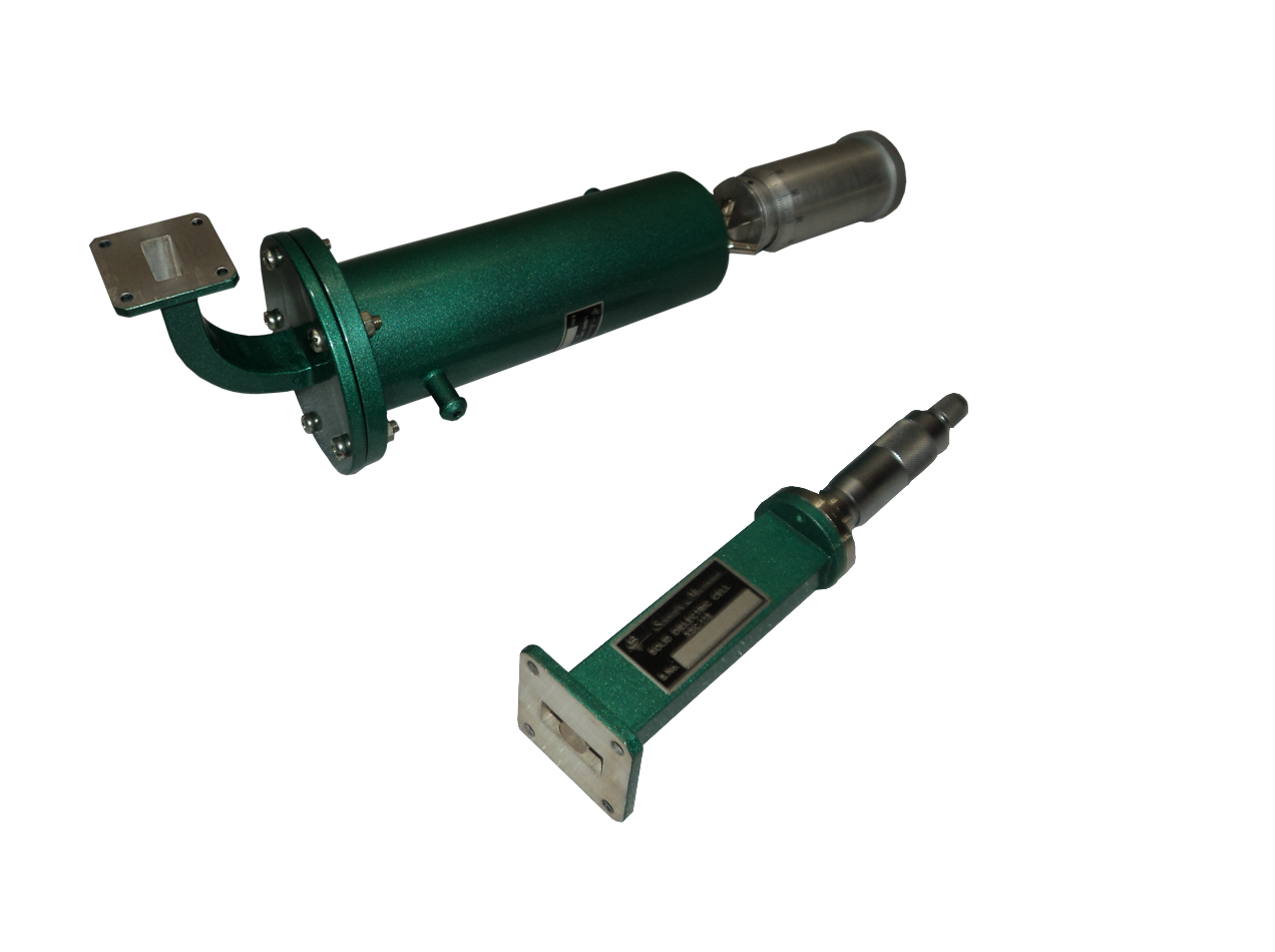
Specifications
| Model | Band | Freq. Range (GHz) | Waveguide | O/P Connector | Crystal Diode |
|---|---|---|---|---|---|
| TL-124 | S | 2.60 - 3.95 | WR-284 | BNC(F) | IN21 |
| TL-124 | C | 3.95 - 5.85 | WR-229 | BNC(F) | IN21 |
| TL-124 | J | 5.85 - 8.20 | WR-137 | BNC(F) | IN23 |
| TL-124 | X | 8.20 - 12.40 | WR-90 | BNC(F) | IN23 |
| TL-124 | Ku | 12.40 - 18.00 | WR-62 | BNC(F) | IN23 |
| TL-124 | K | 18.00 - 26.50 | WR-42 | BNC(F) | IN23 |
Matched Termination
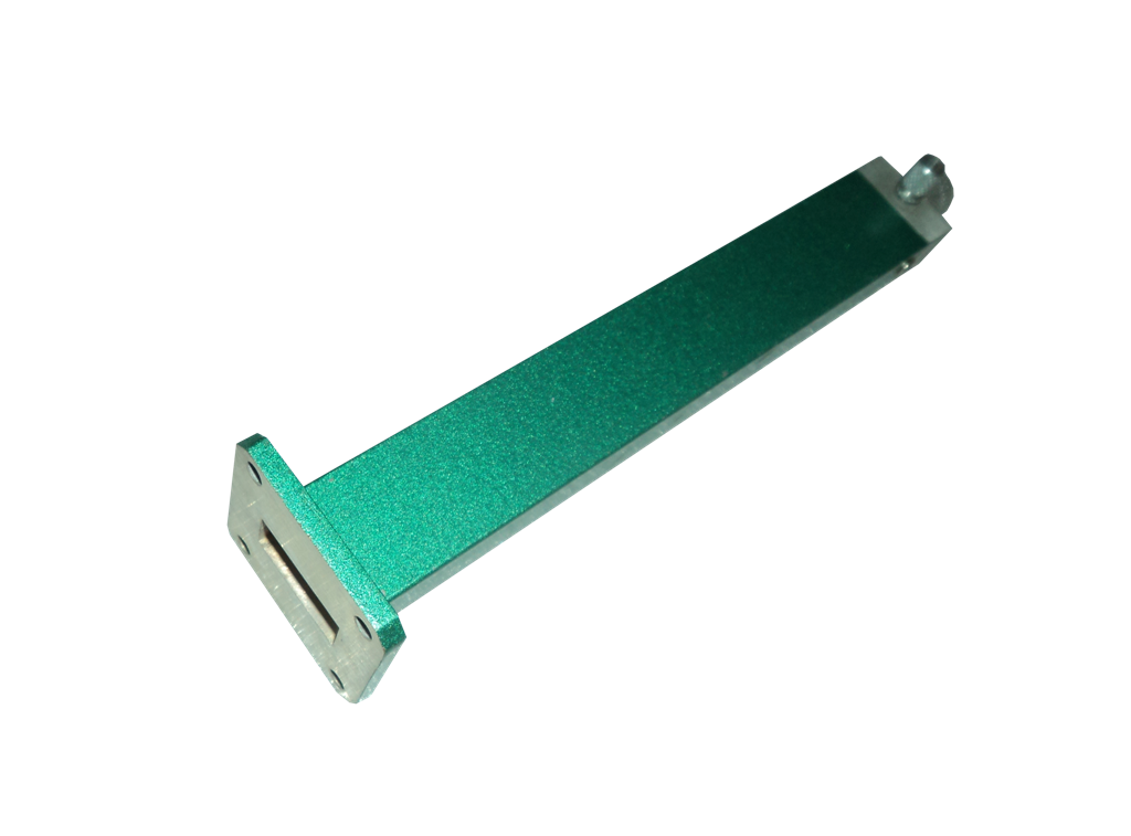
A waveguide termination that absorbs microwave energy with minimal reflections, ensuring accurate experimental measurements.
Specifications
| Model | Band | Freq. Range (GHz) | Waveguide | O/P Connector | Crystal Diode |
|---|---|---|---|---|---|
| TL-124 | S | 2.60 - 3.95 | WR-284 | BNC(F) | IN21 |
| TL-124 | C | 3.95 - 5.85 | WR-229 | BNC(F) | IN21 |
| TL-124 | J | 5.85 - 8.20 | WR-137 | BNC(F) | IN23 |
| TL-124 | X | 8.20 - 12.40 | WR-90 | BNC(F) | IN23 |
| TL-124 | Ku | 12.40 - 18.00 | WR-62 | BNC(F) | IN23 |
| TL-124 | K | 18.00 - 26.50 | WR-42 | BNC(F) | IN23 |
Moveable Short/ Moveable Precision Short

Provides adjustable short-circuit termination for standing wave and impedance measurement experiments in microwave systems.
Specifications
| Model | Band | Freq. Range (GHz) | Waveguide | O/P Connector | Crystal Diode |
|---|---|---|---|---|---|
| TL-124 | S | 2.60 - 3.95 | WR-284 | BNC(F) | IN21 |
| TL-124 | C | 3.95 - 5.85 | WR-229 | BNC(F) | IN21 |
| TL-124 | J | 5.85 - 8.20 | WR-137 | BNC(F) | IN23 |
| TL-124 | X | 8.20 - 12.40 | WR-90 | BNC(F) | IN23 |
| TL-124 | Ku | 12.40 - 18.00 | WR-62 | BNC(F) | IN23 |
| TL-124 | K | 18.00 - 26.50 | WR-42 | BNC(F) | IN23 |
Fixed attenuators
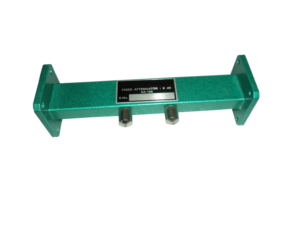
Precision attenuation devices that provide a constant reduction in microwave power for stable and repeatable experimental conditions.
Specifications
| Model | Band | Freq. Range (GHz) | Waveguide | O/P Connector | Crystal Diode |
|---|---|---|---|---|---|
| TL-124 | S | 2.60 - 3.95 | WR-284 | BNC(F) | IN21 |
| TL-124 | C | 3.95 - 5.85 | WR-229 | BNC(F) | IN21 |
| TL-124 | J | 5.85 - 8.20 | WR-137 | BNC(F) | IN23 |
| TL-124 | X | 8.20 - 12.40 | WR-90 | BNC(F) | IN23 |
| TL-124 | Ku | 12.40 - 18.00 | WR-62 | BNC(F) | IN23 |
| TL-124 | K | 18.00 - 26.50 | WR-42 | BNC(F) | IN23 |
Circulator & Isolator
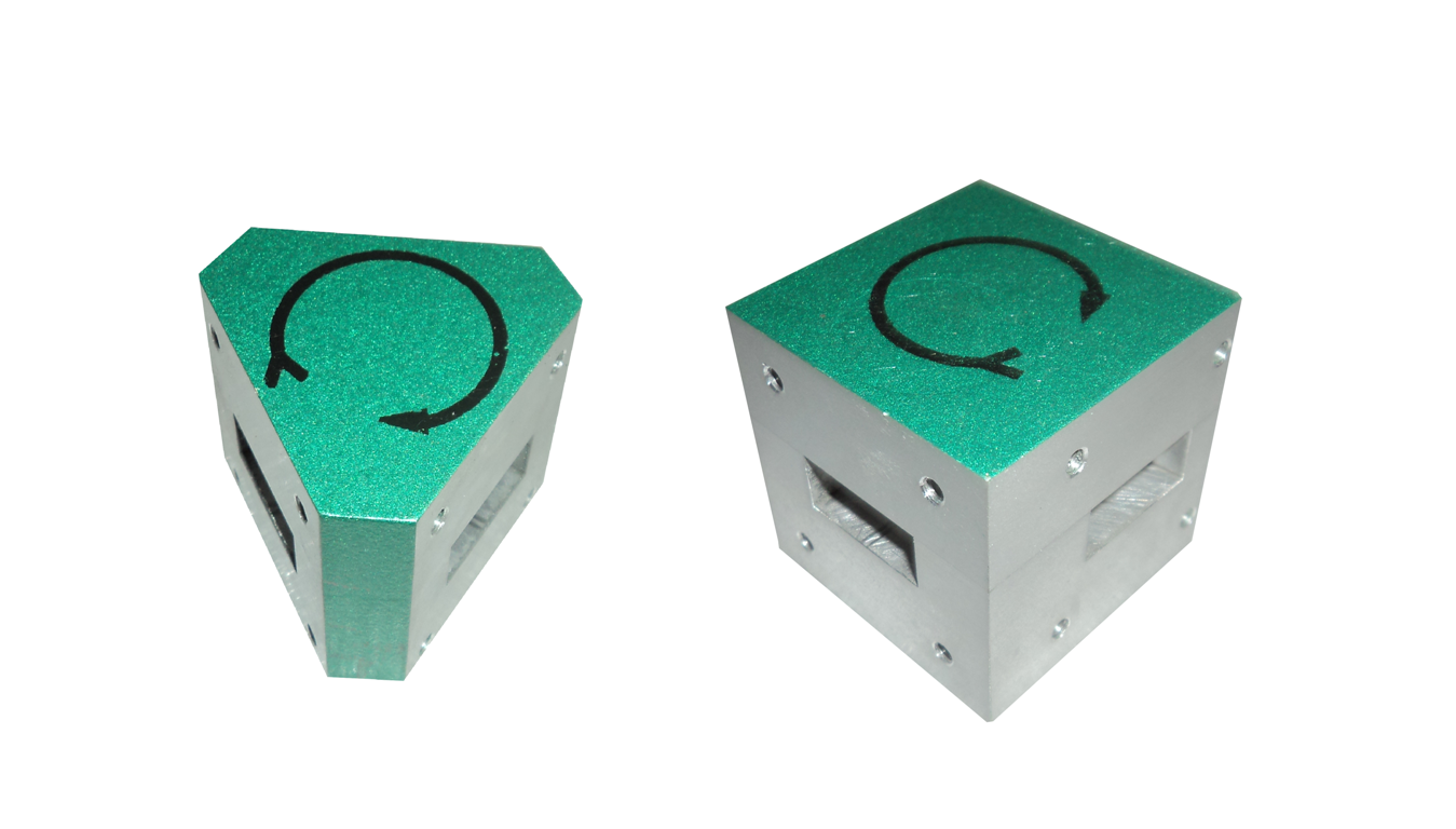
Circulator
Essential microwave components that control signal direction and minimize unwanted reflections, ensuring stable and reliable system performance.
Specifications
| Model | Band | Freq. Range (GHz) | Waveguide | O/P Connector | Crystal Diode |
|---|---|---|---|---|---|
| TL-124 | S | 2.60 - 3.95 | WR-284 | BNC(F) | IN21 |
| TL-124 | C | 3.95 - 5.85 | WR-229 | BNC(F) | IN21 |
| TL-124 | J | 5.85 - 8.20 | WR-137 | BNC(F) | IN23 |
| TL-124 | X | 8.20 - 12.40 | WR-90 | BNC(F) | IN23 |
| TL-124 | Ku | 12.40 - 18.00 | WR-62 | BNC(F) | IN23 |
| TL-124 | K | 18.00 - 26.50 | WR-42 | BNC(F) | IN23 |
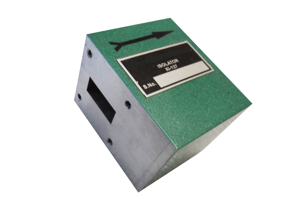
Isolator
A non-reciprocal microwave device that allows signal transmission in one direction while protecting sensitive equipment from reflected power.
Specifications
| Model | Band | Freq. Range (GHz) | Waveguide | O/P Connector | Crystal Diode |
|---|---|---|---|---|---|
| TL-124 | S | 2.60 - 3.95 | WR-284 | BNC(F) | IN21 |
| TL-124 | C | 3.95 - 5.85 | WR-229 | BNC(F) | IN21 |
| TL-124 | J | 5.85 - 8.20 | WR-137 | BNC(F) | IN23 |
| TL-124 | X | 8.20 - 12.40 | WR-90 | BNC(F) | IN23 |
| TL-124 | Ku | 12.40 - 18.00 | WR-62 | BNC(F) | IN23 |
| TL-124 | K | 18.00 - 26.50 | WR-42 | BNC(F) | IN23 |
Coaxial To Waveguide Adaptors
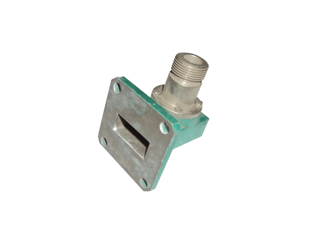
Designed to efficiently transition microwave signals between coaxial cables and waveguide systems with minimal insertion loss.
Specifications
| Model | Band | Freq. Range (GHz) | Waveguide | O/P Connector | Crystal Diode |
|---|---|---|---|---|---|
| TL-124 | S | 2.60 - 3.95 | WR-284 | BNC(F) | IN21 |
| TL-124 | C | 3.95 - 5.85 | WR-229 | BNC(F) | IN21 |
| TL-124 | J | 5.85 - 8.20 | WR-137 | BNC(F) | IN23 |
| TL-124 | X | 8.20 - 12.40 | WR-90 | BNC(F) | IN23 |
| TL-124 | Ku | 12.40 - 18.00 | WR-62 | BNC(F) | IN23 |
| TL-124 | K | 18.00 - 26.50 | WR-42 | BNC(F) | IN23 |
Cross Directional Coupler
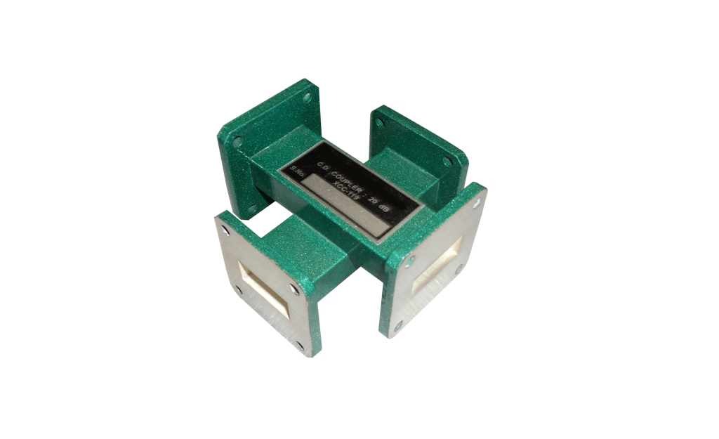
A specialized directional coupler used for accurate forward and reverse power measurements in microwave transmission systems.
Specifications
| Model | Band | Freq. Range (GHz) | Waveguide | O/P Connector | Crystal Diode |
|---|---|---|---|---|---|
| TL-124 | S | 2.60 - 3.95 | WR-284 | BNC(F) | IN21 |
| TL-124 | C | 3.95 - 5.85 | WR-229 | BNC(F) | IN21 |
| TL-124 | J | 5.85 - 8.20 | WR-137 | BNC(F) | IN23 |
| TL-124 | X | 8.20 - 12.40 | WR-90 | BNC(F) | IN23 |
| TL-124 | Ku | 12.40 - 18.00 | WR-62 | BNC(F) | IN23 |
| TL-124 | K | 18.00 - 26.50 | WR-42 | BNC(F) | IN23 |
Detector Mount
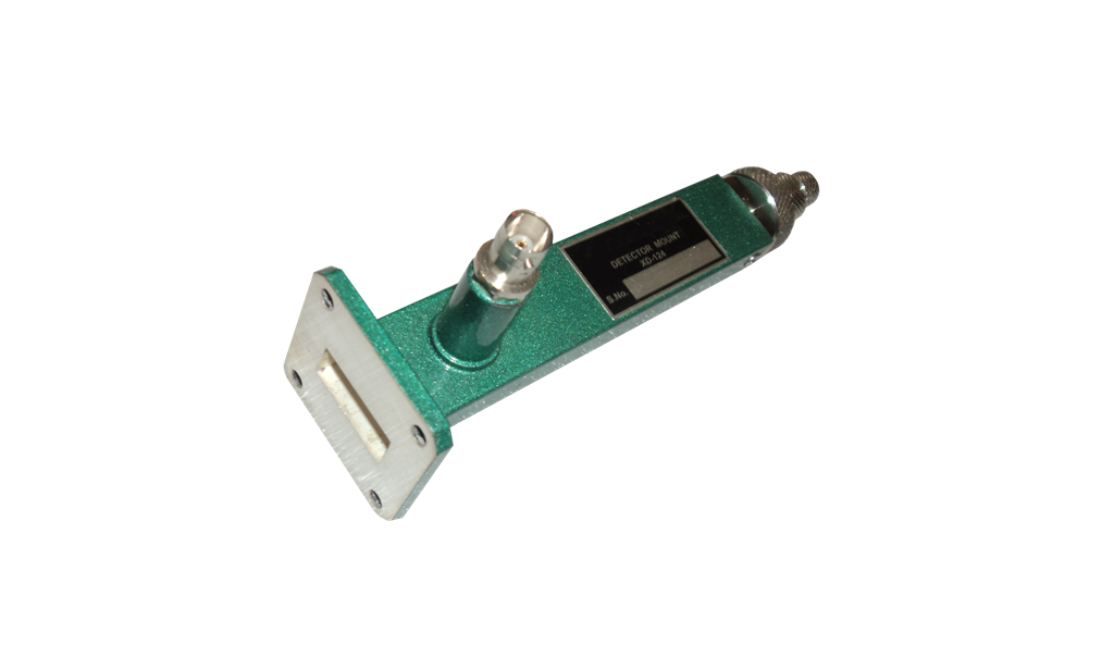
Houses the microwave detector diode and converts microwave energy into measurable electrical signals for analysis and experimentation.
Specifications
| Model | Band | Freq. Range (GHz) | Waveguide | O/P Connector | Crystal Diode |
|---|---|---|---|---|---|
| TL-124 | S | 2.60 - 3.95 | WR-284 | BNC(F) | IN21 |
| TL-124 | C | 3.95 - 5.85 | WR-229 | BNC(F) | IN21 |
| TL-124 | J | 5.85 - 8.20 | WR-137 | BNC(F) | IN23 |
| TL-124 | X | 8.20 - 12.40 | WR-90 | BNC(F) | IN23 |
| TL-124 | Ku | 12.40 - 18.00 | WR-62 | BNC(F) | IN23 |
| TL-124 | K | 18.00 - 26.50 | WR-42 | BNC(F) | IN23 |
E & H Plane Bends
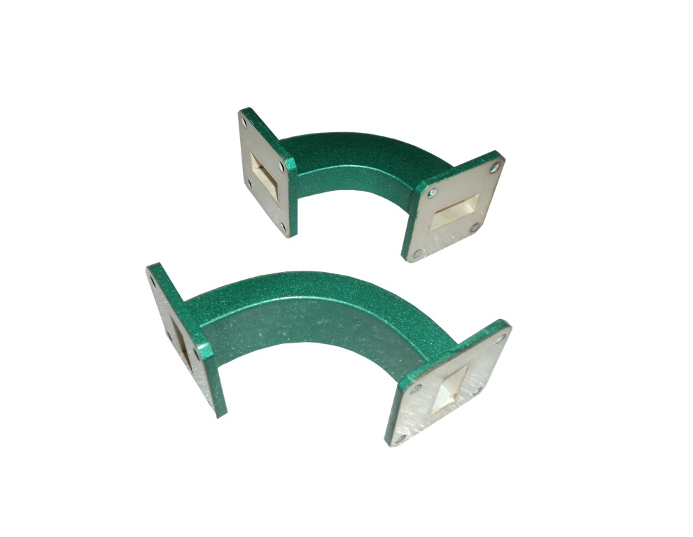
Waveguide bends engineered to change signal direction while maintaining optimal microwave transmission performance.
Specifications
| Model | Band | Freq. Range (GHz) | Waveguide | O/P Connector | Crystal Diode |
|---|---|---|---|---|---|
| TL-124 | S | 2.60 - 3.95 | WR-284 | BNC(F) | IN21 |
| TL-124 | C | 3.95 - 5.85 | WR-229 | BNC(F) | IN21 |
| TL-124 | J | 5.85 - 8.20 | WR-137 | BNC(F) | IN23 |
| TL-124 | X | 8.20 - 12.40 | WR-90 | BNC(F) | IN23 |
| TL-124 | Ku | 12.40 - 18.00 | WR-62 | BNC(F) | IN23 |
| TL-124 | K | 18.00 - 26.50 | WR-42 | BNC(F) | IN23 |
E-Plane, H-Plane and Magic Tee
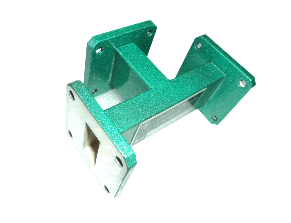
E-Plane TEE
Precision waveguide junctions used for signal splitting, combining, and microwave network analysis in laboratory experiments.
Specifications
| Model | Band | Freq. Range (GHz) | Waveguide | Calibration | VSWR |
|---|---|---|---|---|---|
| TL-125 | S | 2.60 - 3.95 | WR-284 | 10 | 1.03 |
| TL-125 | C | 3.95 - 5.85 | WR-229 | 10 | 1.03 |
| TL-125 | J | 5.85 - 8.20 | WR-137 | 10 | 1.03 |
| TL-125 | X | 8.20 - 12.40 | WR-90 | 10 | 1.03 |
| TL-125 | Ku | 12.40 - 18.00 | WR-62 | 10 | 1.03 |
| TL-125 | K | 18.00 - 26.50 | WR-42 | 10 | 1.03 |
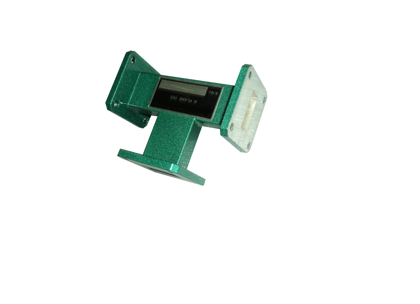
H-Plane TEE
An H-Plane TEE is a waveguide TEE in which the axis of its side arm is shunting the E field or parallel to the H field of the main guide and attaching the another waveguide.
Specifications
| Model | Band | Freq. Range (GHz) | Waveguide | Calibration | VSWR |
|---|---|---|---|---|---|
| TL-125 | S | 2.60 - 3.95 | WR-284 | 10 | 1.03 |
| TL-125 | C | 3.95 - 5.85 | WR-229 | 10 | 1.03 |
| TL-125 | J | 5.85 - 8.20 | WR-137 | 10 | 1.03 |
| TL-125 | X | 8.20 - 12.40 | WR-90 | 10 | 1.03 |
| TL-125 | Ku | 12.40 - 18.00 | WR-62 | 10 | 1.03 |
Attenuators
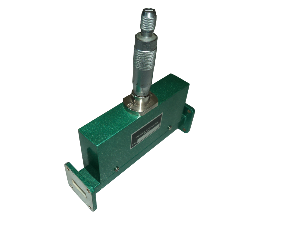
Used to accurately reduce microwave signal power without significantly affecting signal quality, enabling controlled laboratory measurements.
Specifications
| Model | Band | Freq. Range (GHz) | Waveguide | O/P Connector | Crystal Diode |
|---|---|---|---|---|---|
| TL-124 | S | 2.60 - 3.95 | WR-284 | BNC(F) | IN21 |
| TL-124 | C | 3.95 - 5.85 | WR-229 | BNC(F) | IN21 |
| TL-124 | J | 5.85 - 8.20 | WR-137 | BNC(F) | IN23 |
| TL-124 | X | 8.20 - 12.40 | WR-90 | BNC(F) | IN23 |
| TL-124 | Ku | 12.40 - 18.00 | WR-62 | BNC(F) | IN23 |
| TL-124 | K | 18.00 - 26.50 | WR-42 | BNC(F) | IN23 |
Frequently Asked question
What is a Microwave Test Bench?
A Microwave Test Bench is a complete laboratory system used to study microwave engineering concepts through practical experiments. It includes RF and microwave components such as power supplies, waveguides, attenuators, couplers, and measuring instruments, enabling students and researchers to understand microwave transmission, propagation, and measurement techniques.
Who is this Microwave Test Bench designed for?
Our Microwave Test Benches are designed for engineering colleges, universities, research laboratories, defence organisations, and technical training centres offering RF and microwave engineering education.
What experiments can be performed using the Microwave Test Bench?
Depending on the selected model, users can perform experiments including VSWR measurement, frequency and power measurement, waveguide characteristics, directional coupler analysis, attenuator and phase shifter studies, antenna radiation patterns, circulator and isolator characteristics, dielectric constant measurement, and more.
What is the difference between the Gunn Diode and Klystron-based models?
Gunn Diode-based systems are ideal for continuous-wave microwave experiments and simplified laboratory setups, while Klystron-based systems offer a broader range of microwave experiments and are widely used for advanced engineering education and research applications.
Can the Microwave Test Bench be customised?
Yes. Technilab offers customised configurations based on your curriculum, laboratory requirements, experiment list, and institutional needs.
Do you provide installation and technical support?
Yes. We provide installation guidance, technical assistance, product training, and dependable after-sales support to ensure your laboratory operates efficiently
Which Microwave Test Bench model is right for my institution?
Our team will recommend the most suitable model based on your course curriculum, laboratory objectives, number of students, and budget.
Do you supply complete microwave laboratory solutions?
Yes. In addition to Microwave Test Benches, we supply waveguide components, RF instruments, antenna trainer kits, microwave accessories, and customised laboratory solutions to help institutions build complete RF and microwave laboratories
Looking for the Right Microwave Test Bench?
From undergraduate laboratories to advanced research facilities, Technilab offers reliable microwave training systems tailored to your curriculum and laboratory requirements.


Technilab Instrument is a reputed organisation engaged in design, manufacture ,distribute and service provider of Test and Measuring Instruments and RF and microwave components. The company is managed by a team of experienced engineers having vast experience in Instrumentation, Sales and support.